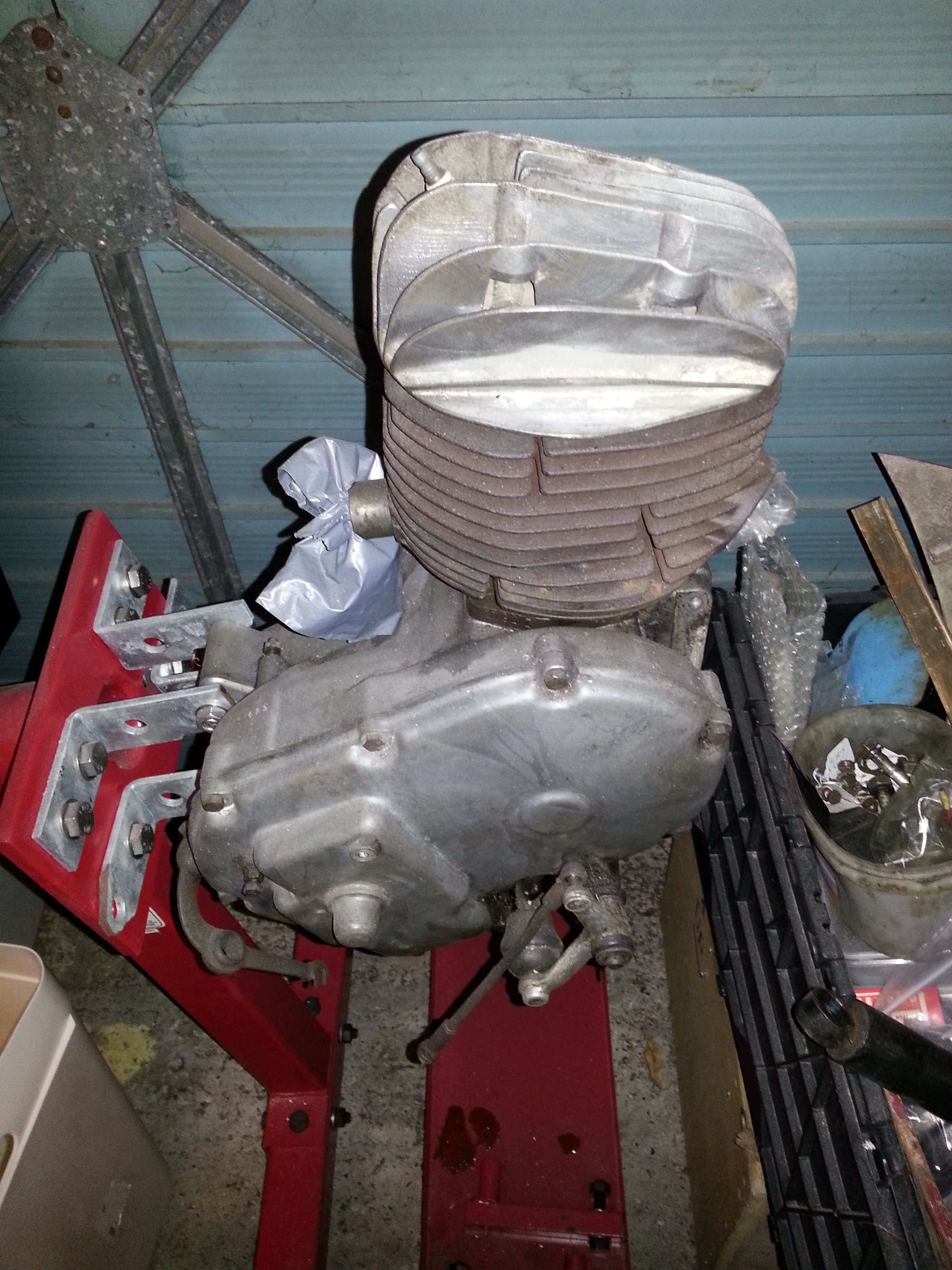
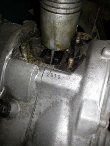
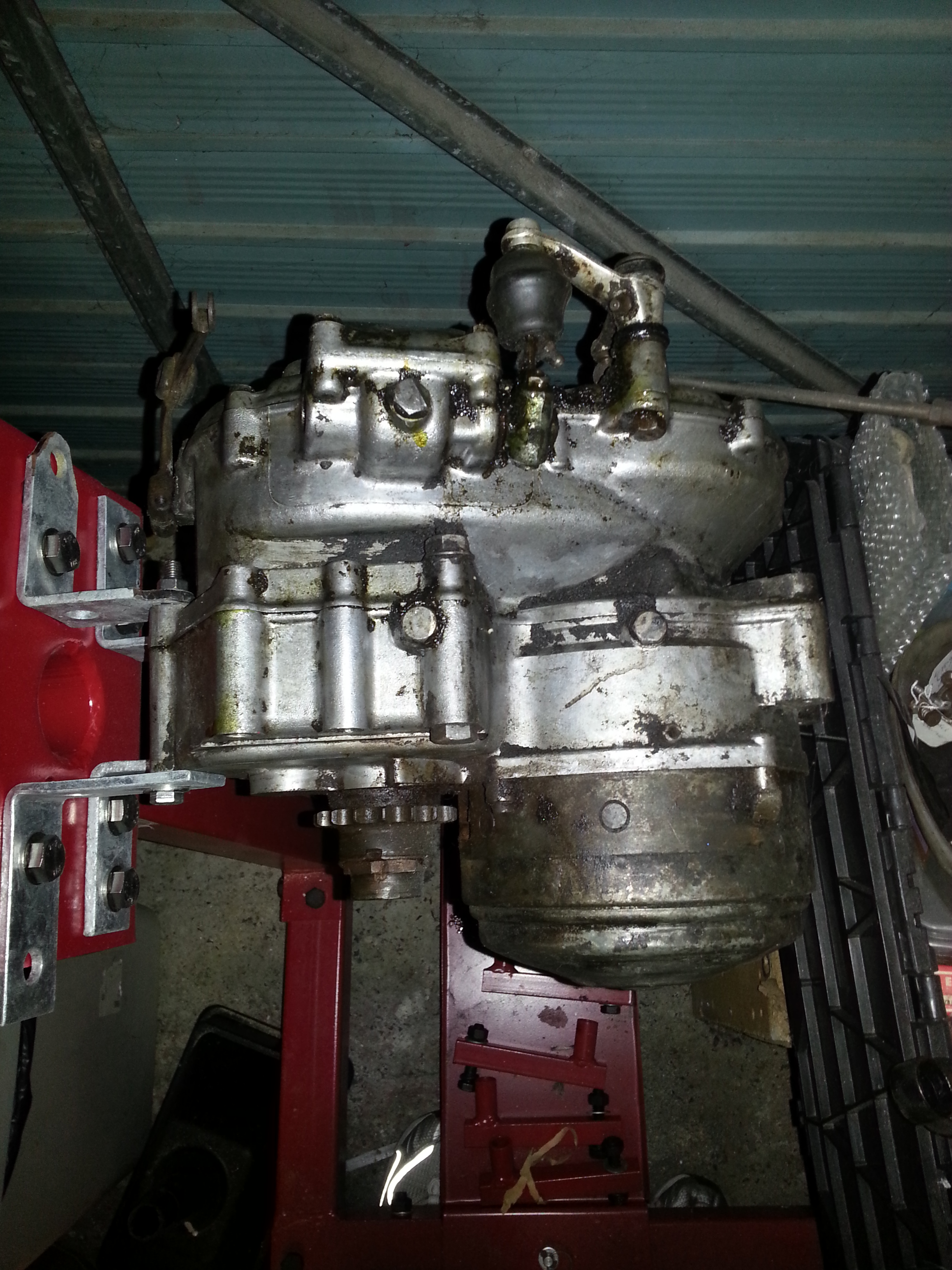
This section will describe disassembly of the Bella R204 engine. Sit tight as it will be quite long, but hopefully useful should you want to take an engine restore on. It’s my first time and looks harder than it is, although I will reserve judgement until it runs again!
First step is to mount the engine in the engine stand which will help the disassembly process:
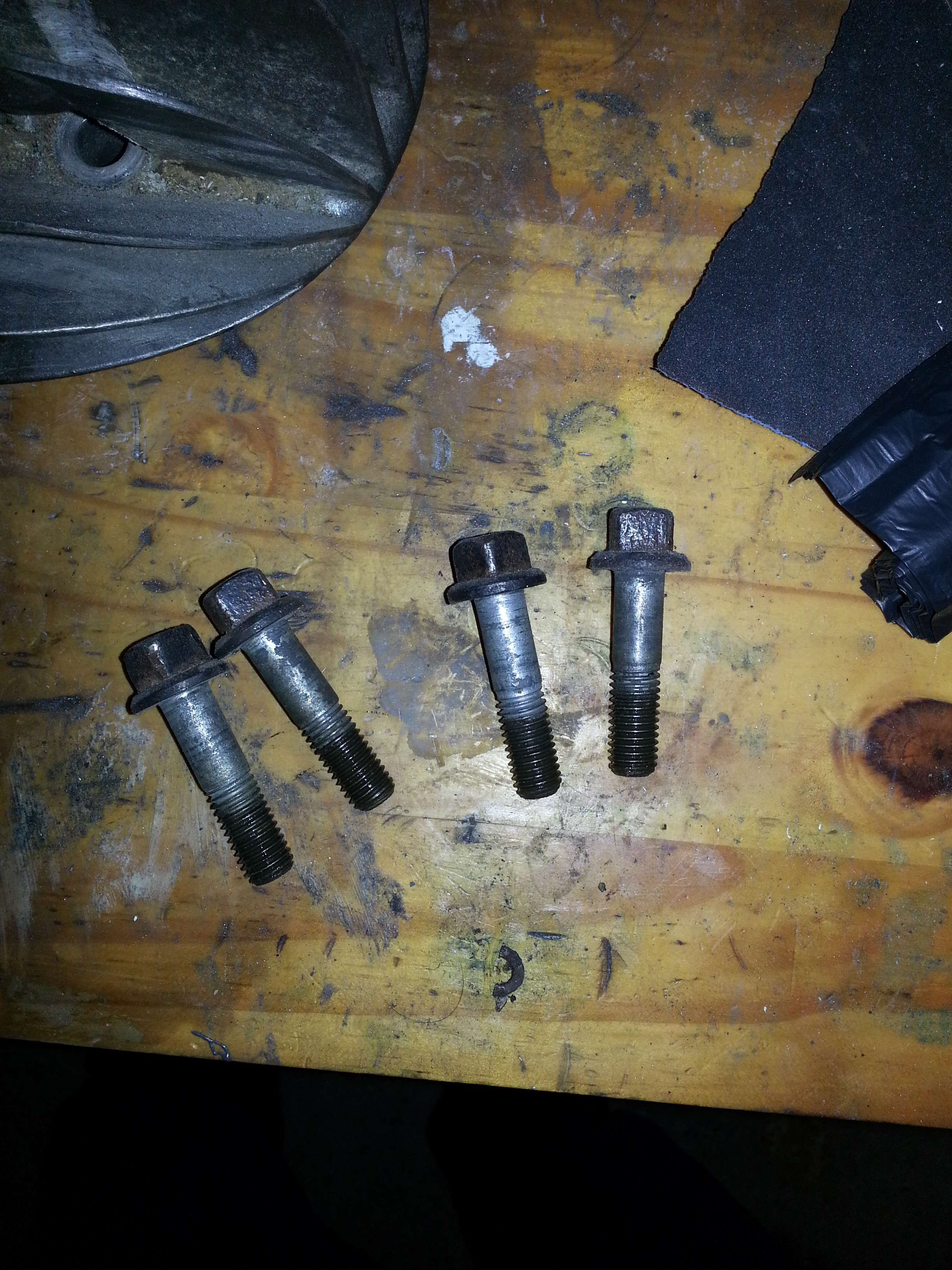
We’ll start with removing the cylinder head. Note that the Zündapp head bolts have a square head. You can order a bespoke square tool from Helmut and Iris Bougé or use a square socket:
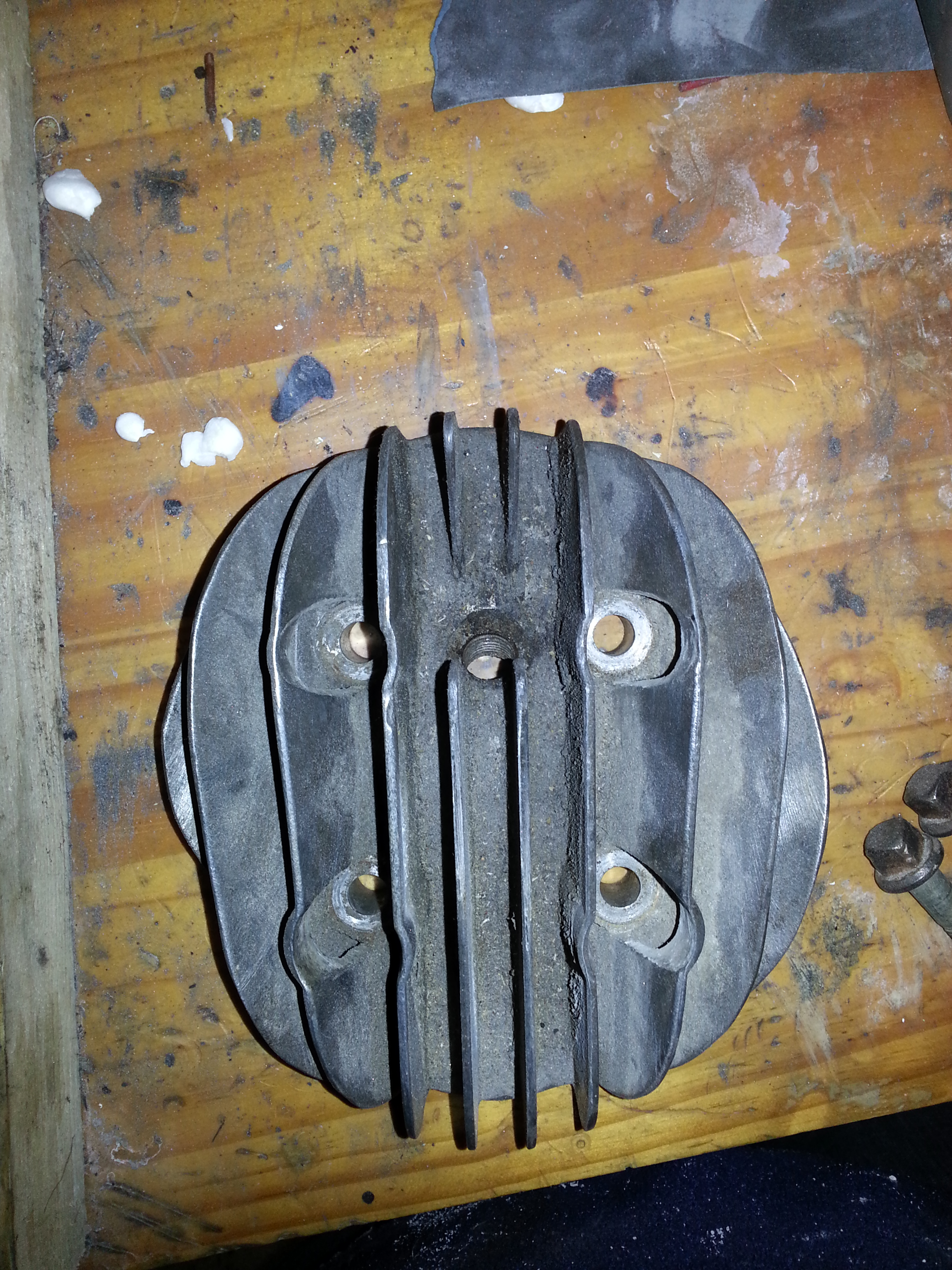
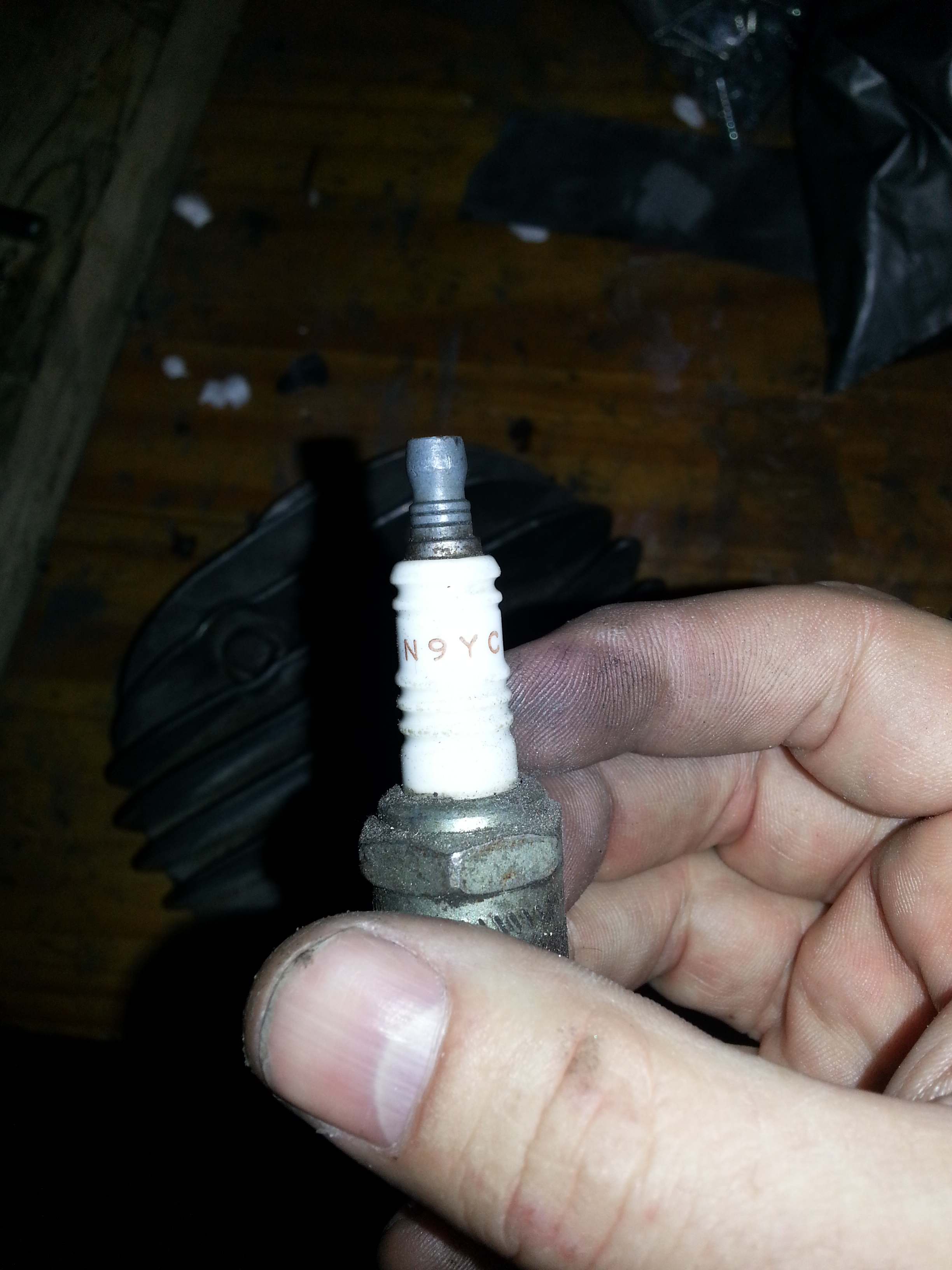
Take care when removing the spark plug; the head and thread are aluminium and can damage easily. My engine had a Champion N9YC plug. I will need to check that’s the right type and not some random spare plug.
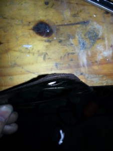
The head gasket is made of laminated metal and coming apart; time to replace it:
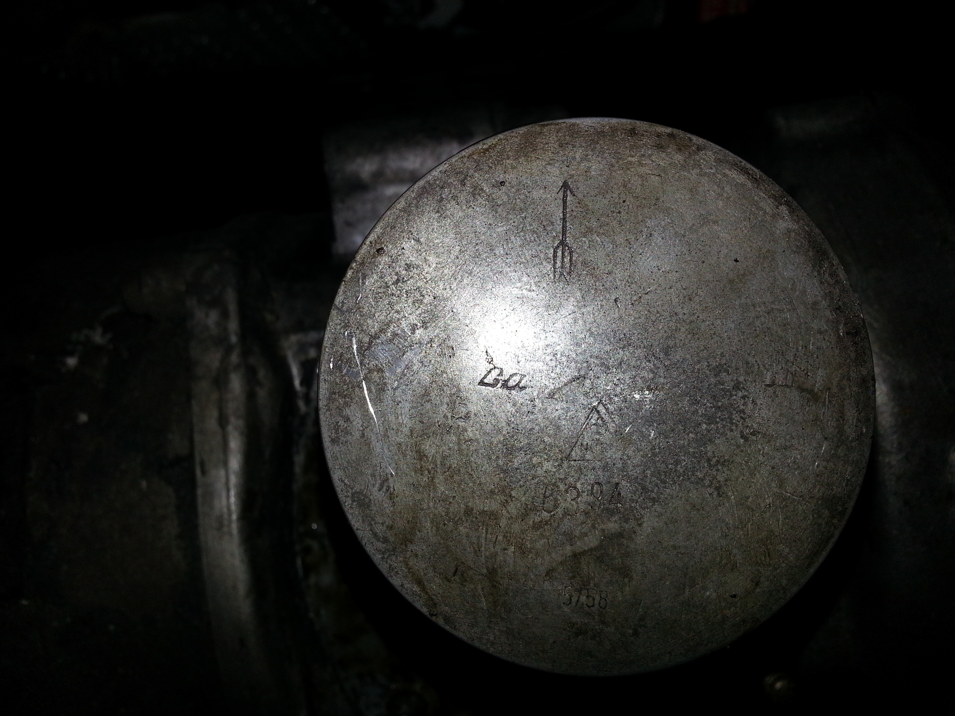
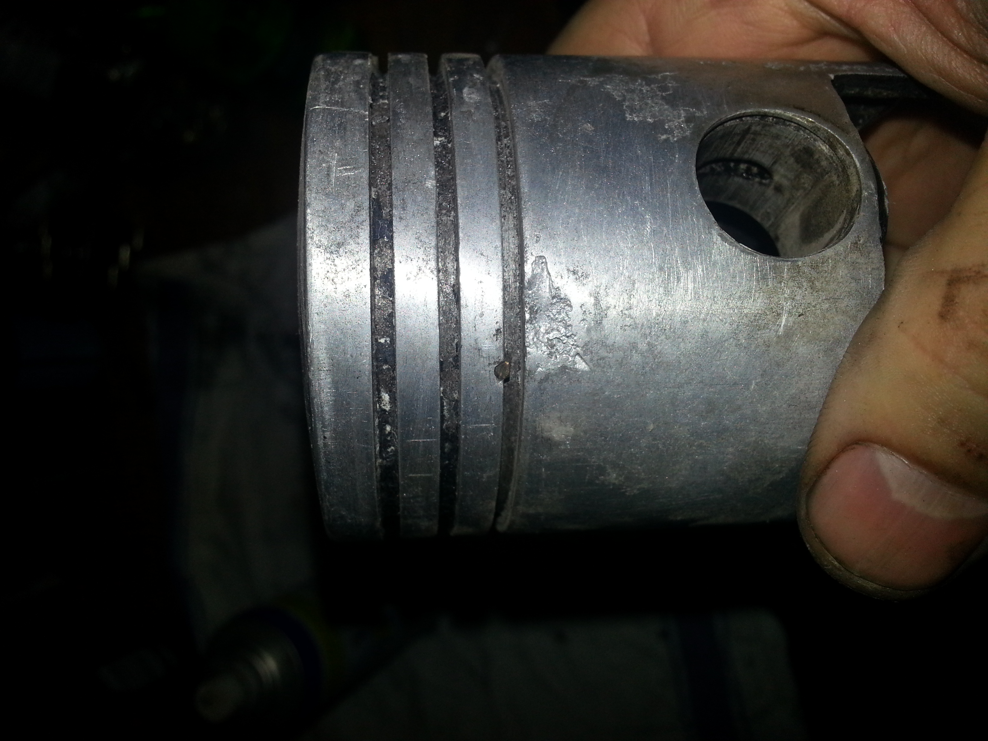
The piston is still the original at 63.94mm. Later on we’ll have to measure the Cylinder to see whether it has worn to the point of needing a rebore and an oversize piston.
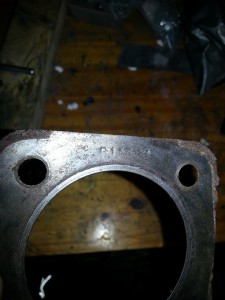
The Cylinder itself looks good and is stamped with a number same to the frame and the engine so all original. Thy cylinder itself is unscratched and looks good.
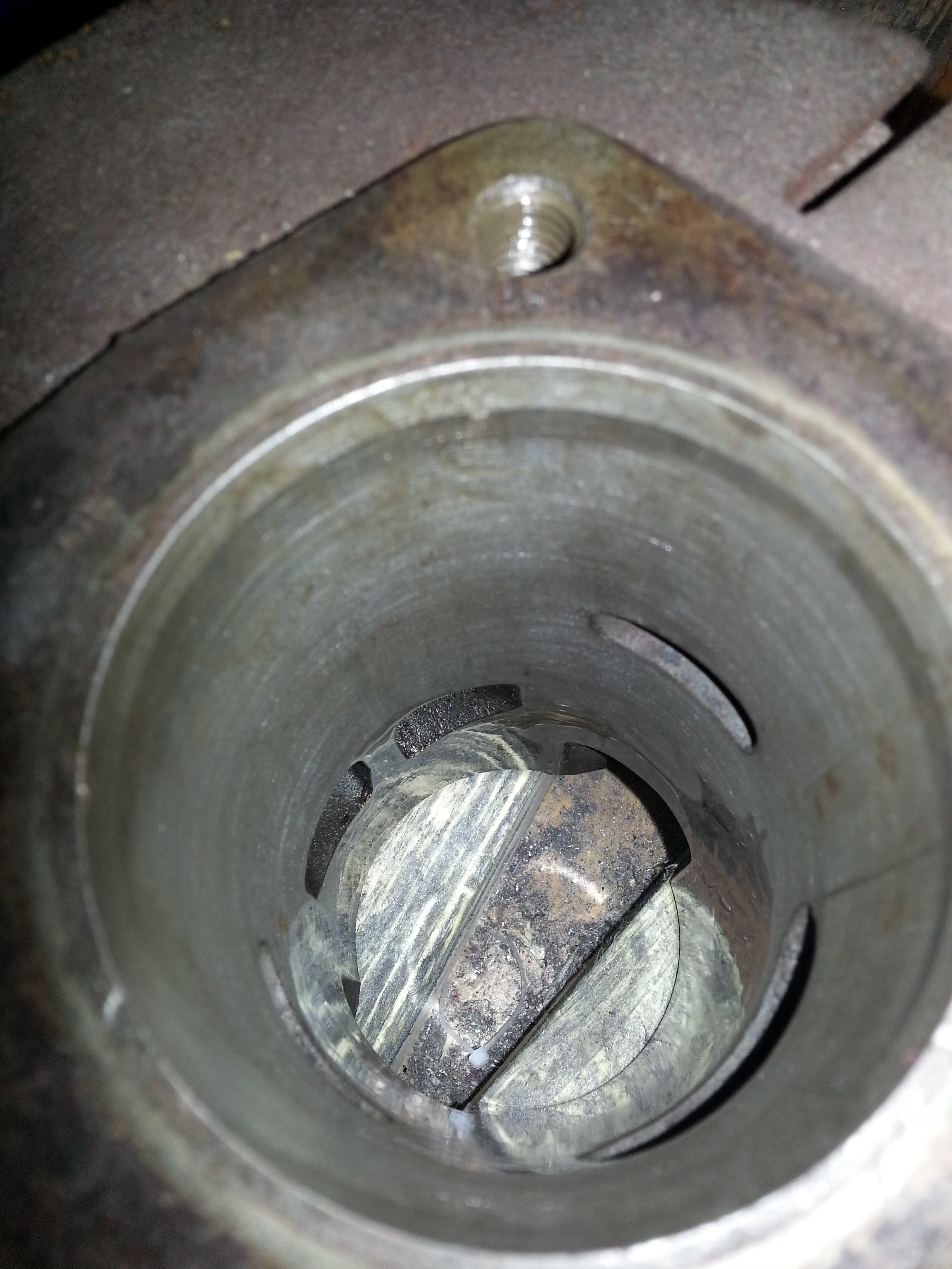
Next it’s time to take the piston out. The circlips came out easily and the piston pin can be pushed out with a little manual effort.
The piston itself however has had it. Pieces have broken off. Having inspected the piston I’m putting it back so we can block internal movement later.
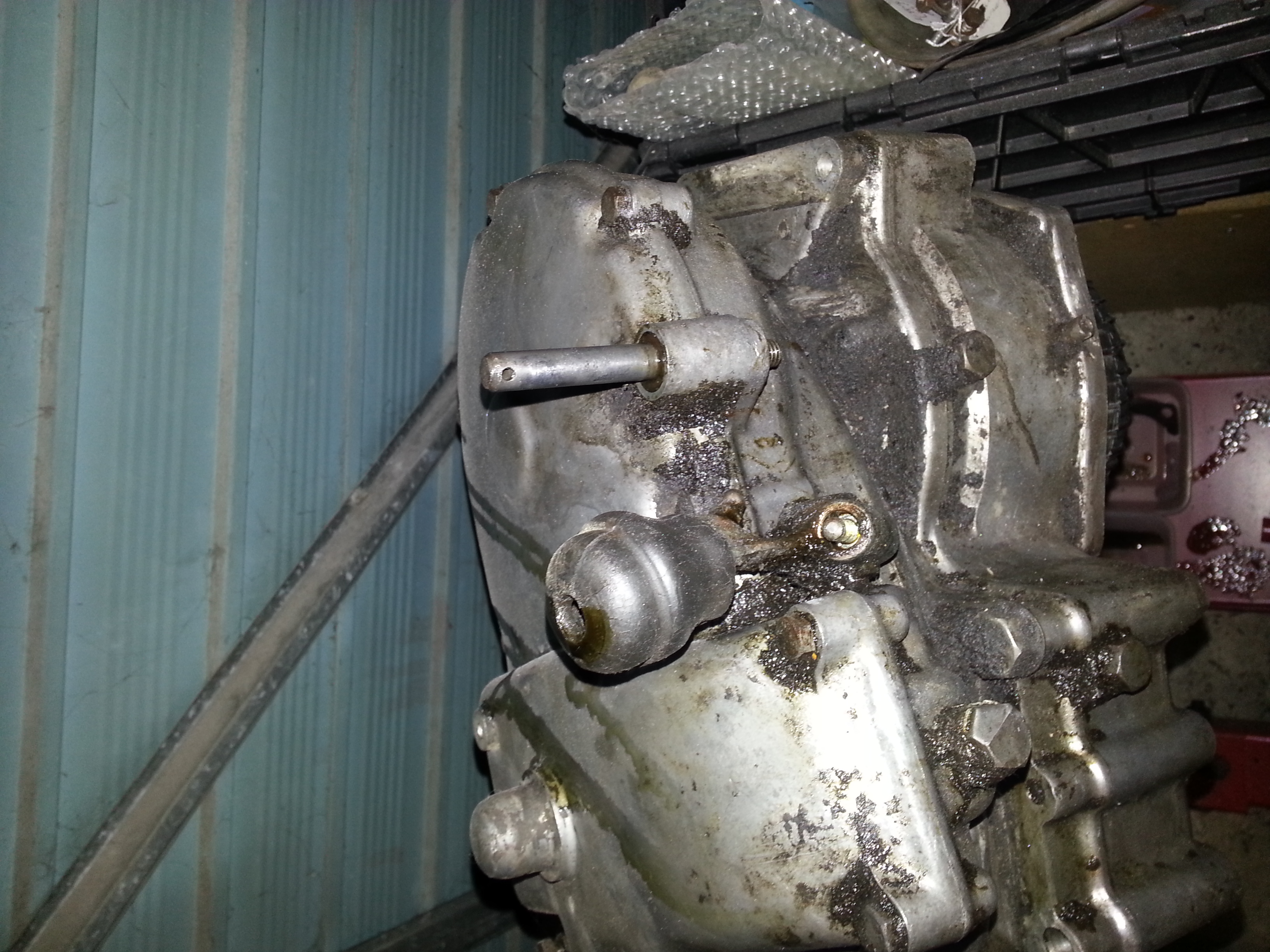
Next we’ll inspect the various levers and pieces on the outside of the engine.
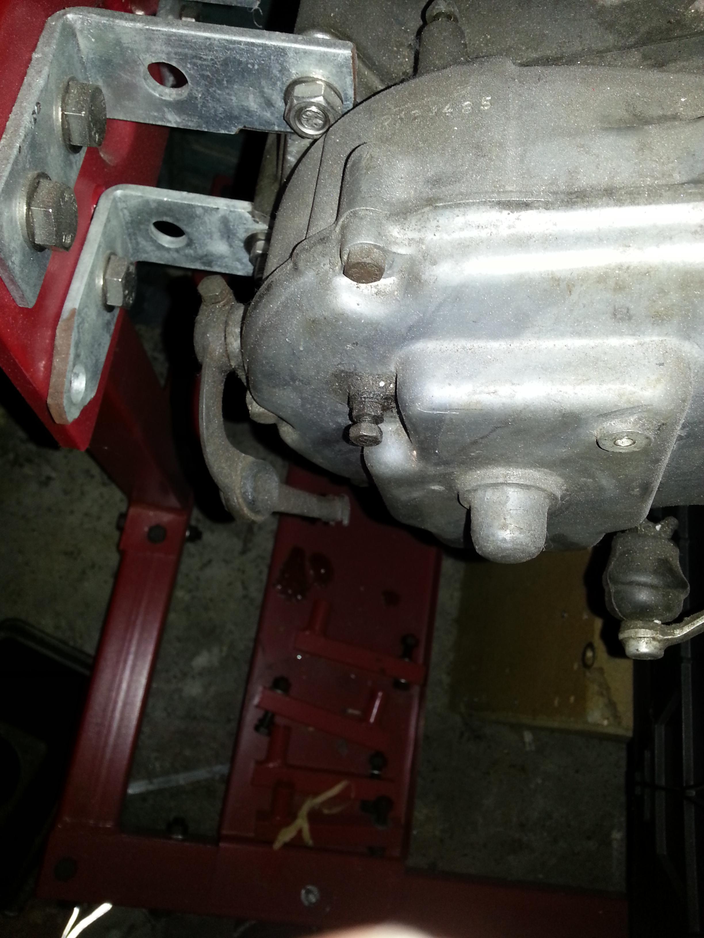
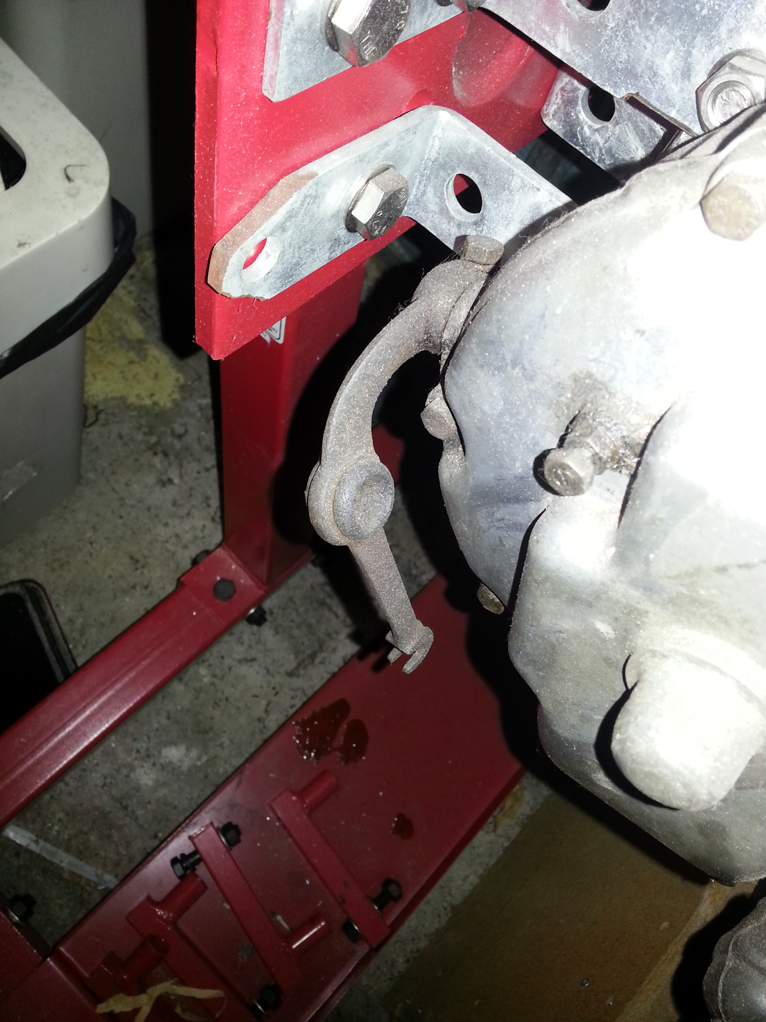
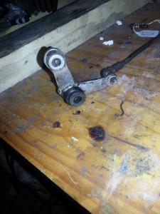
First is the shift lever to remove:
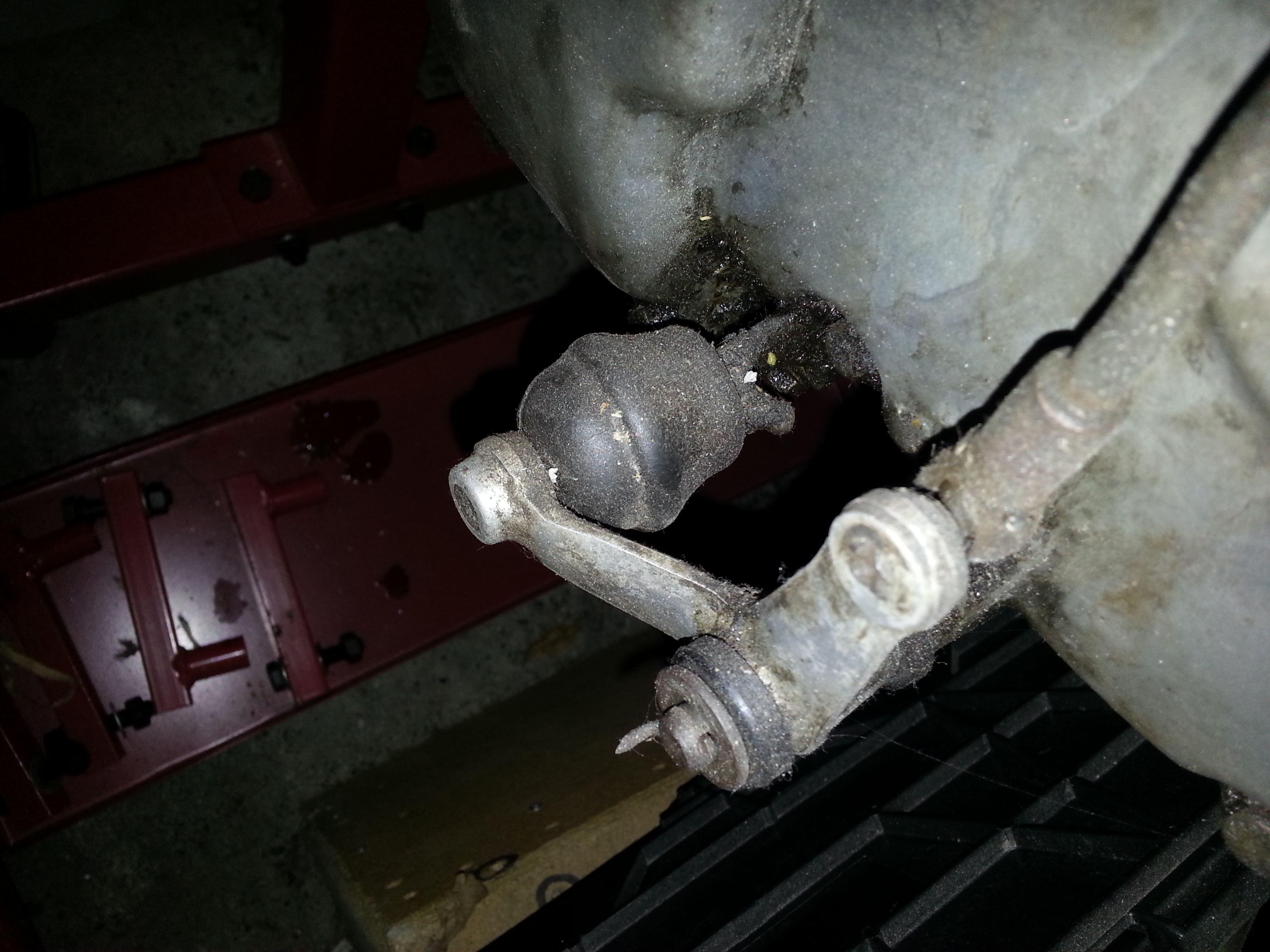
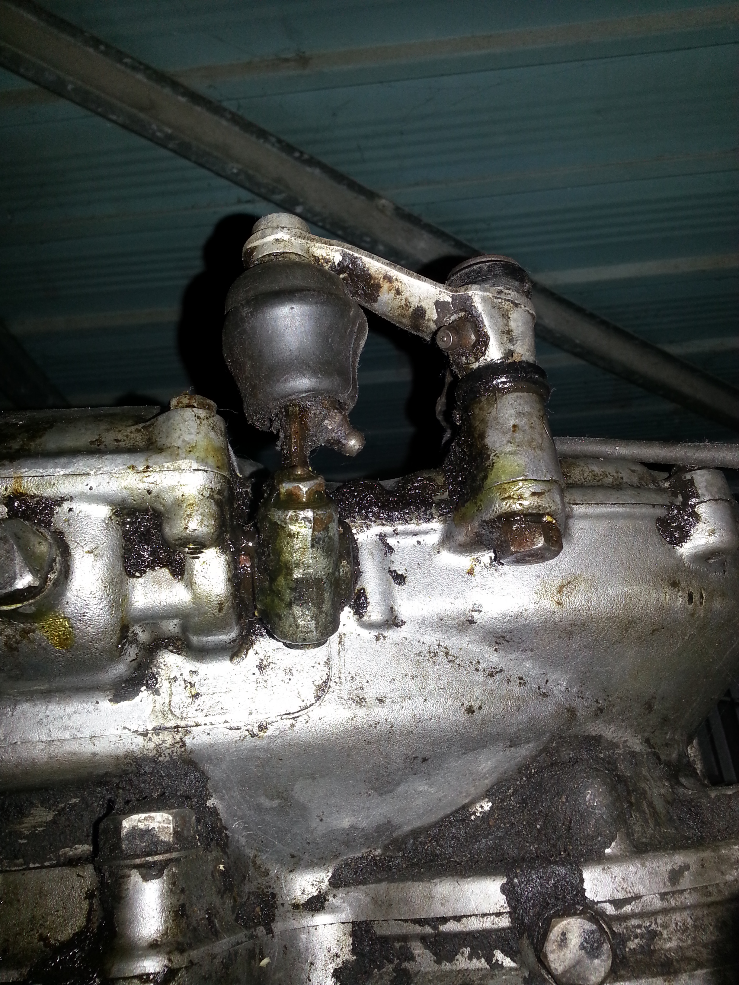
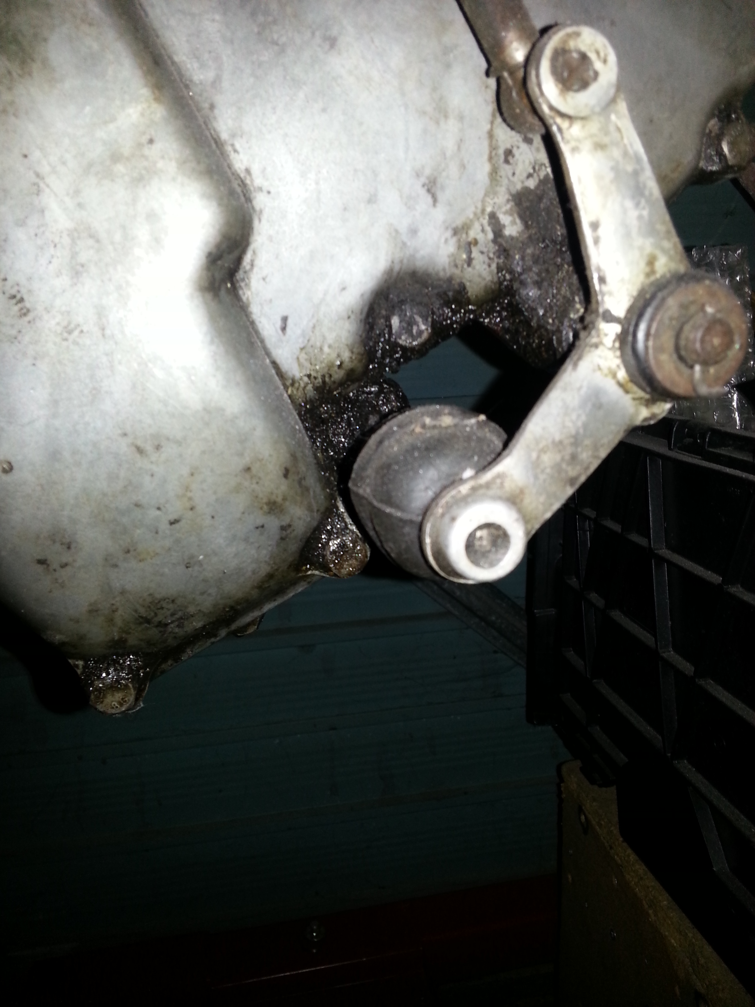
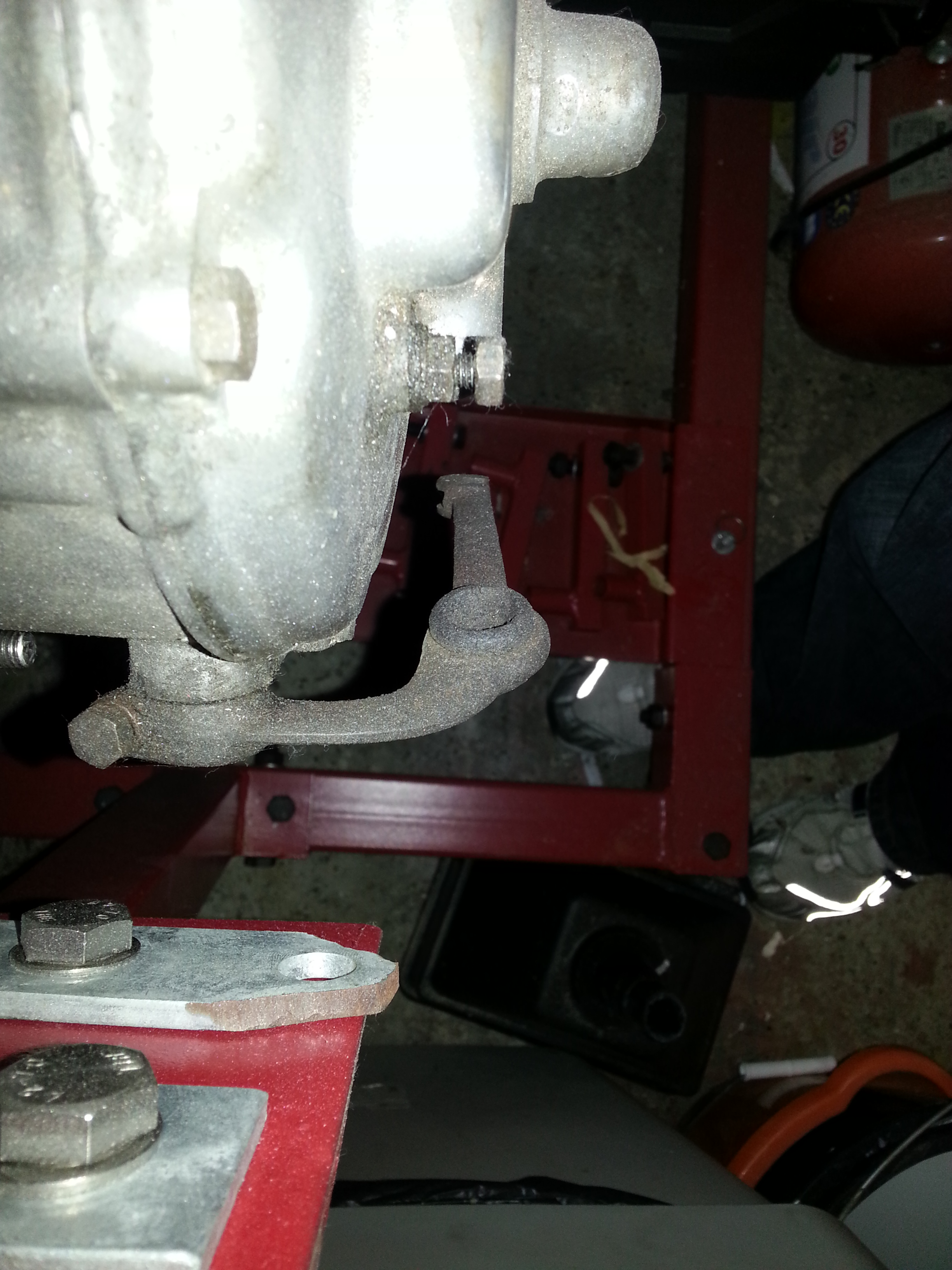
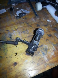
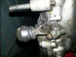
The angle lever is connected to the gearshift rod. The other end of the rod is connected to the footshift lever. The construct is a ball joint and this one’s quite loose and worn. It will have to be replaced. For now we’ll remove it:
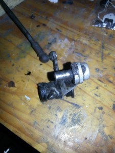
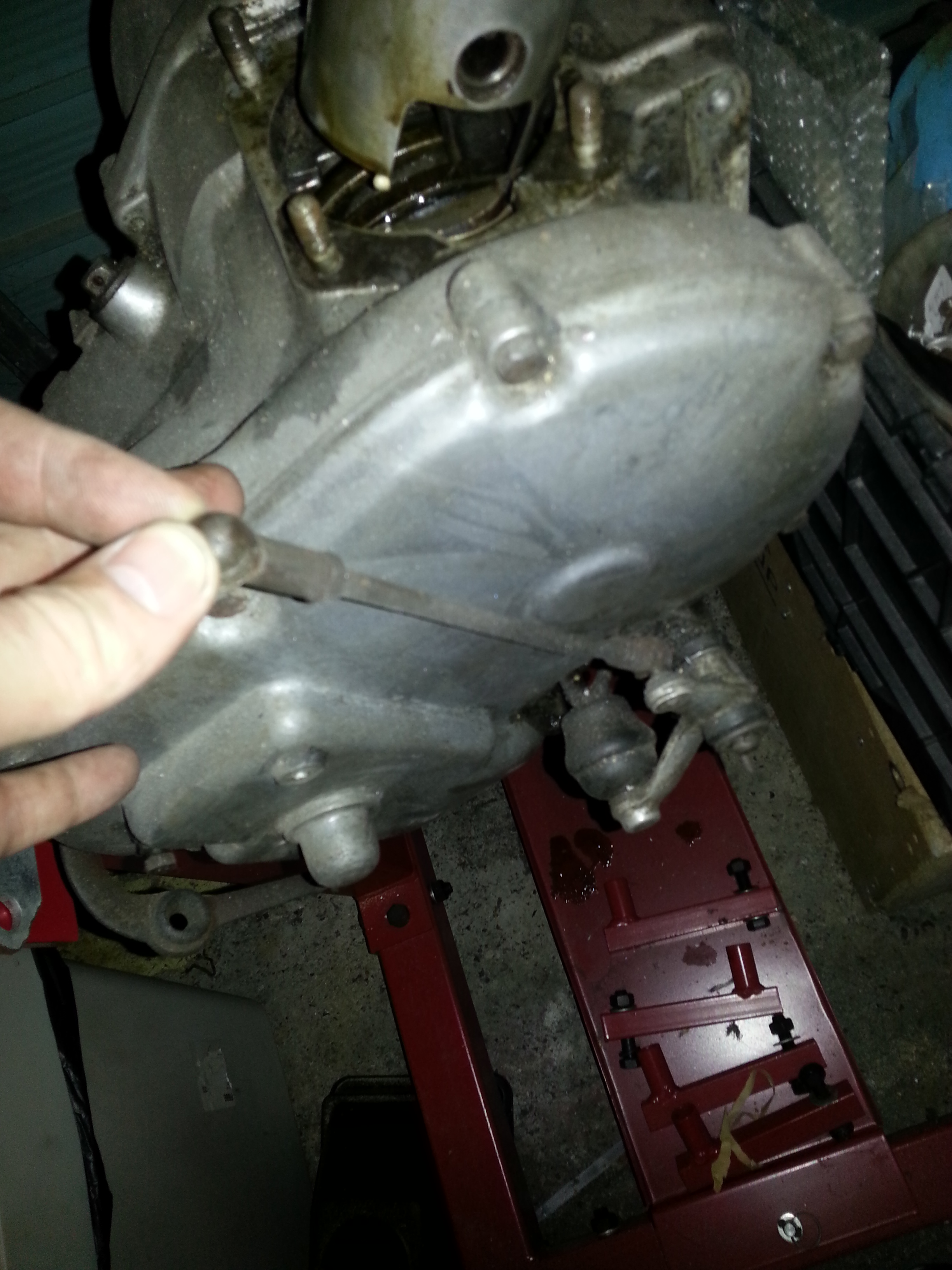
What remains is the gearshift lever. We will remove this later as it will take some time to figure out how to remove it.
The clutch lever needs to be removed too. I pried it off with screwdrivers, but need to find a less ham-fisted way.
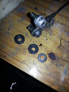
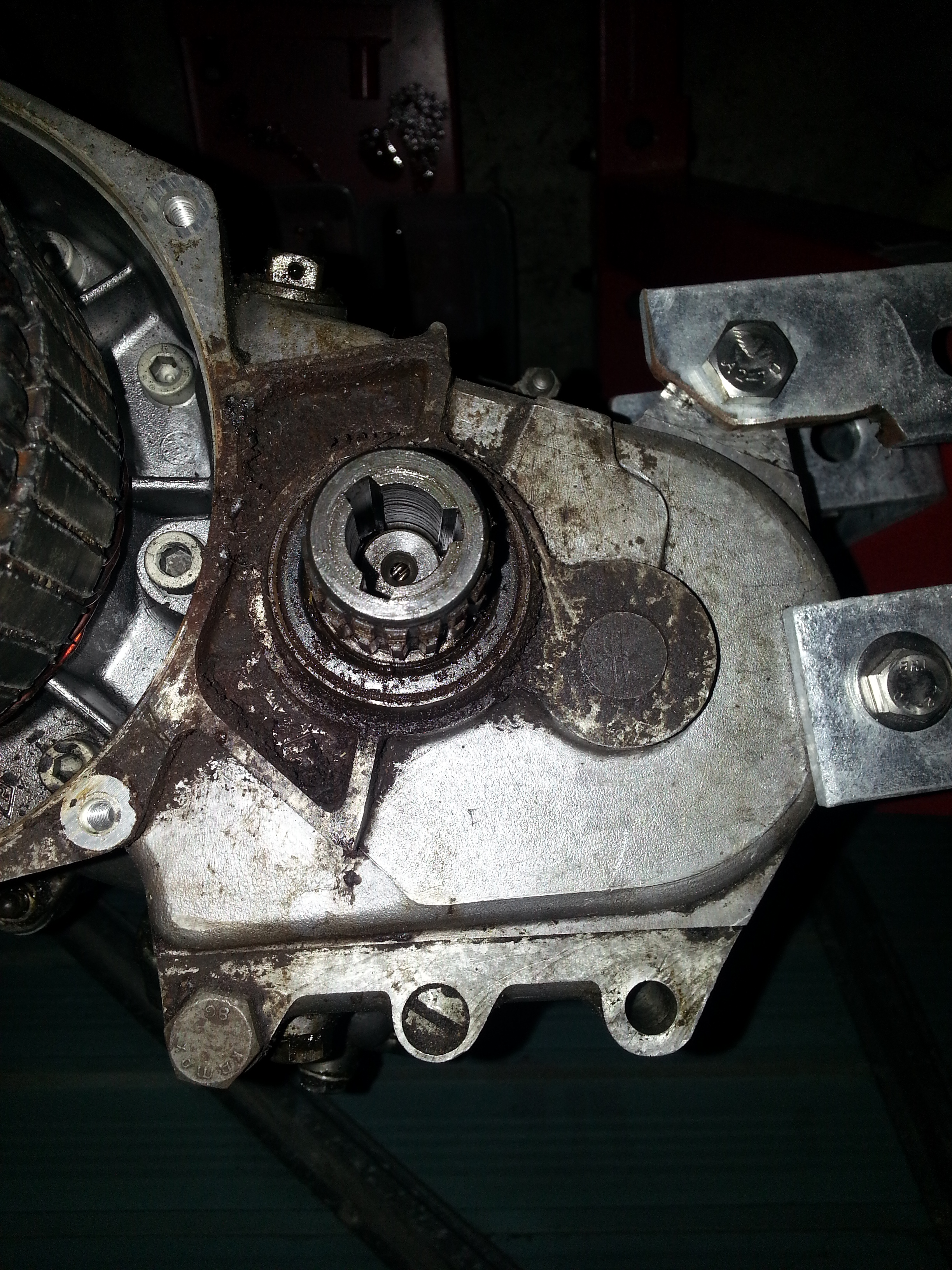
Time to take the final drive sprocket off:
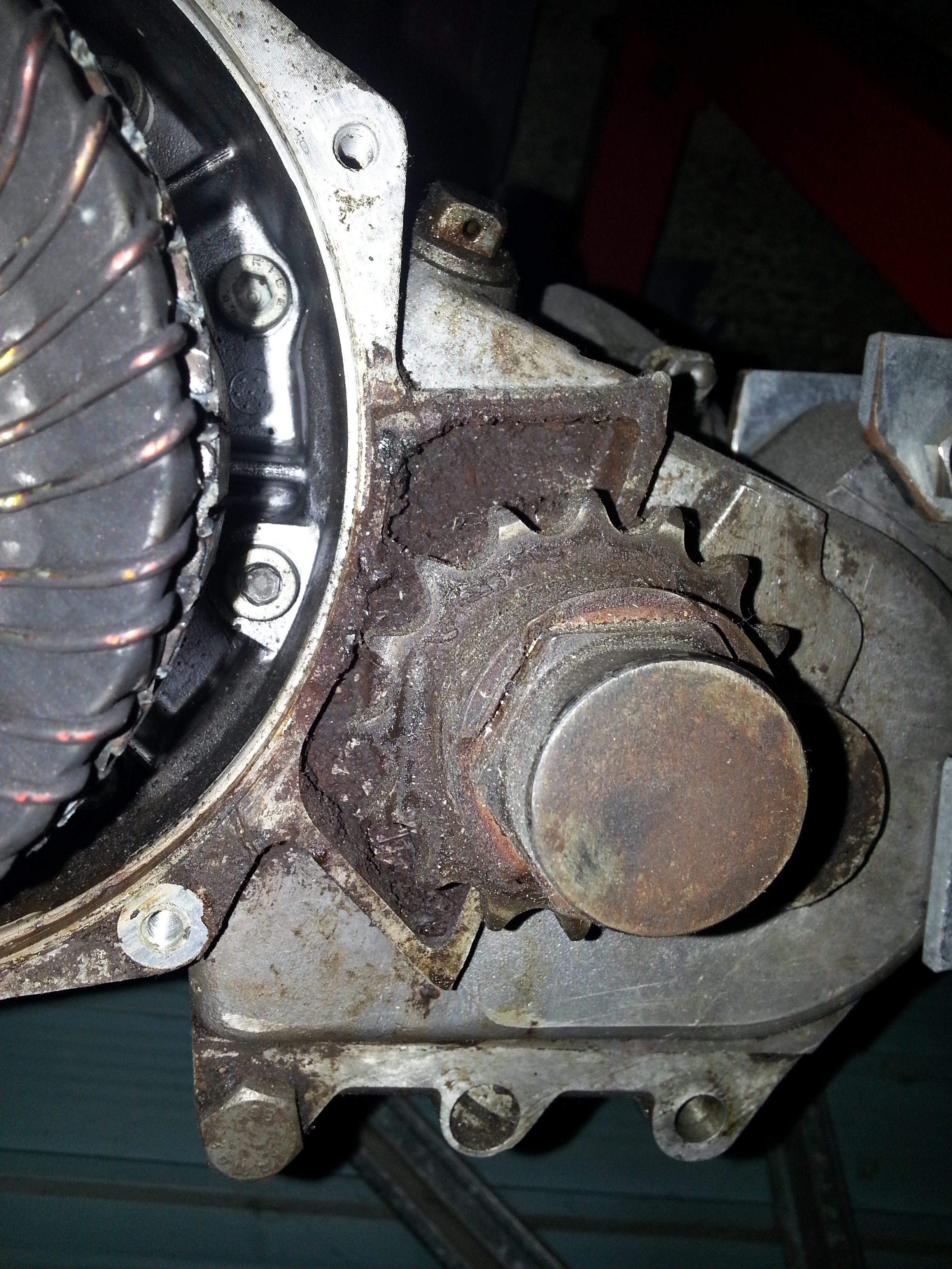
First flatten the retaining washer:
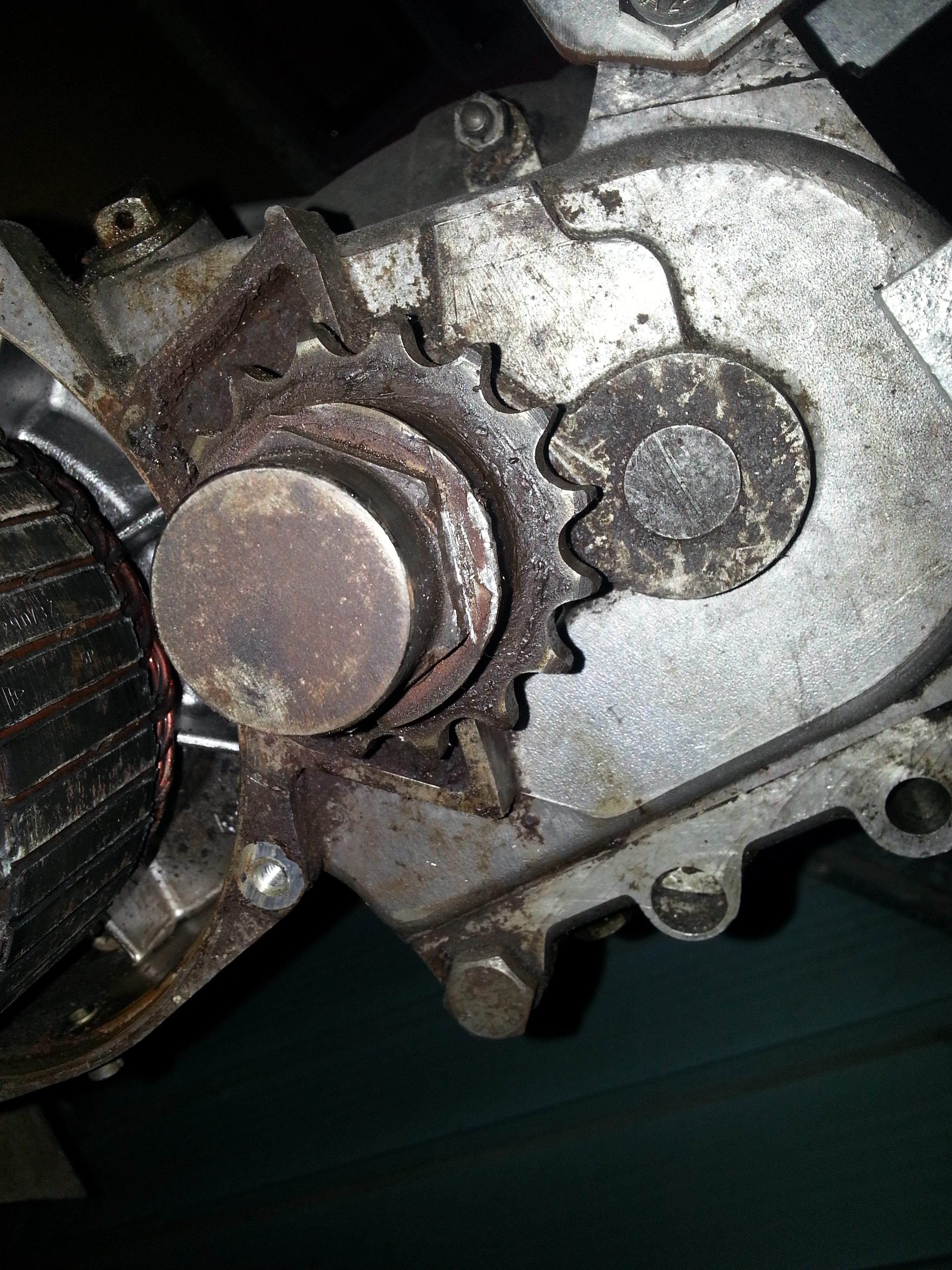
Then remove the lock nut:
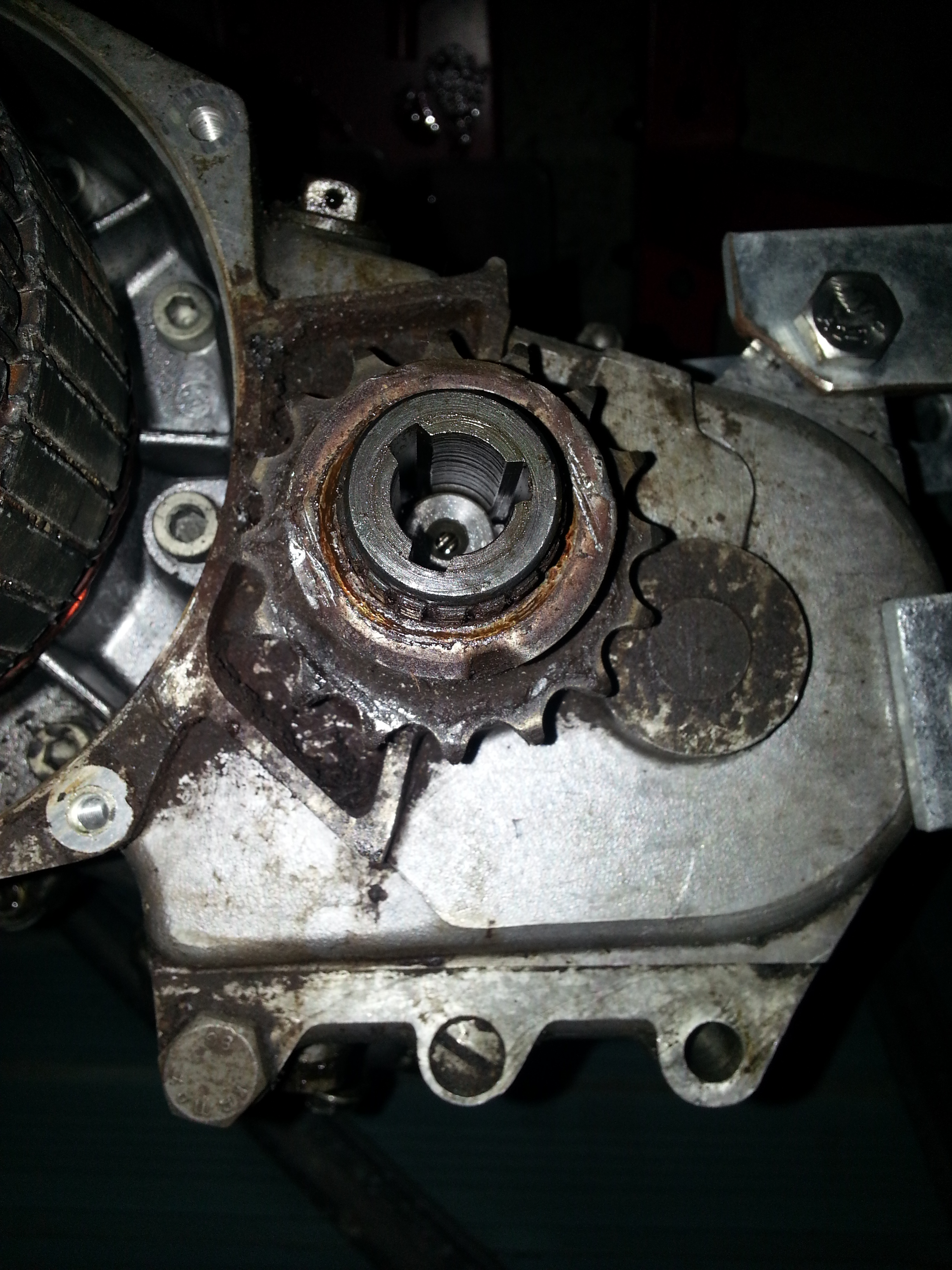
Remember how the locking washer it positioned and remove it:
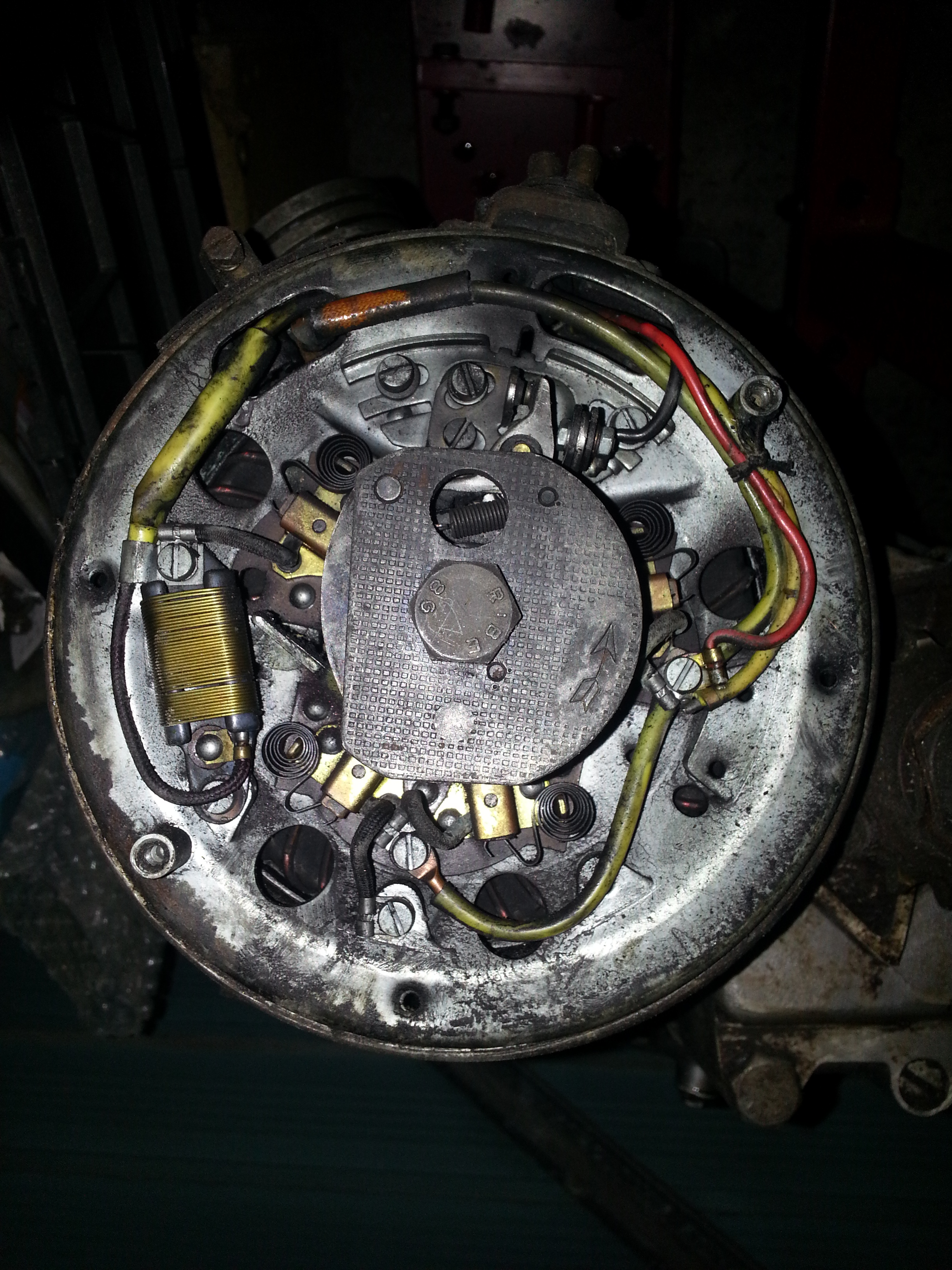
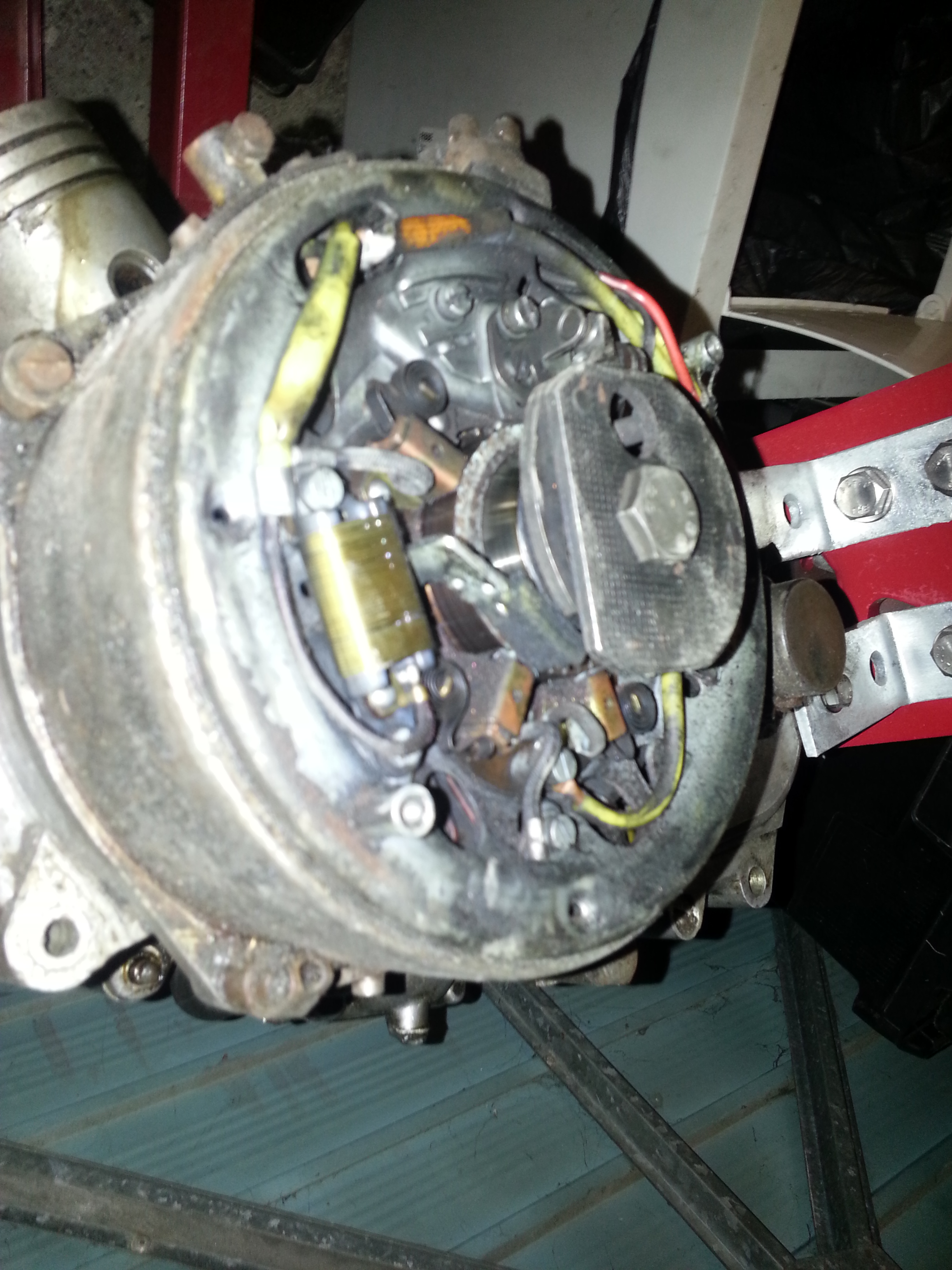
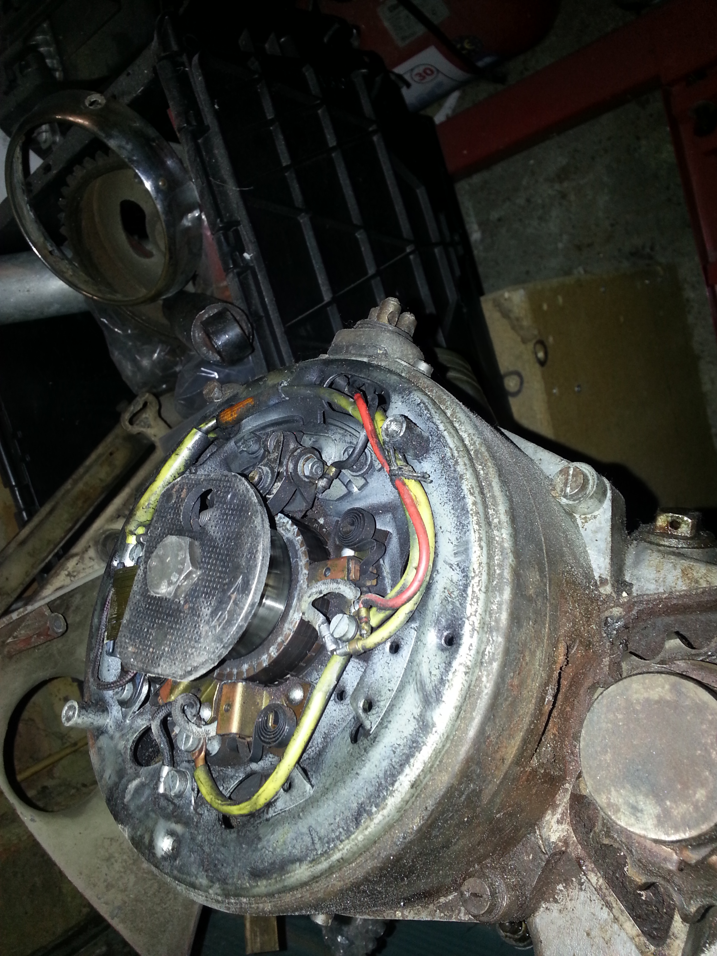
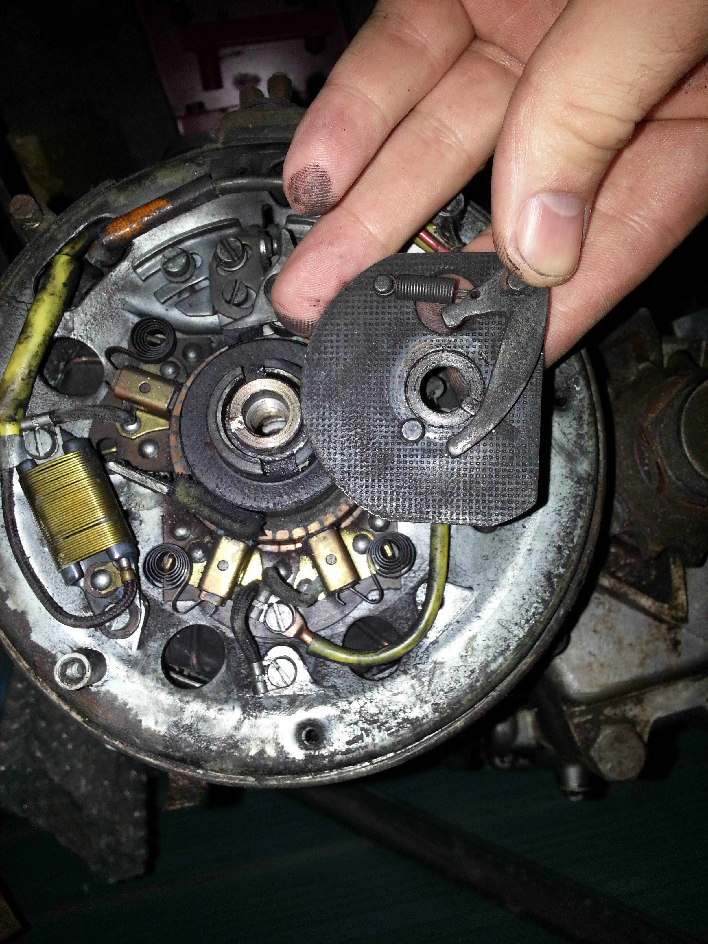
Next is the dynamo cove and the points behind the small cover:
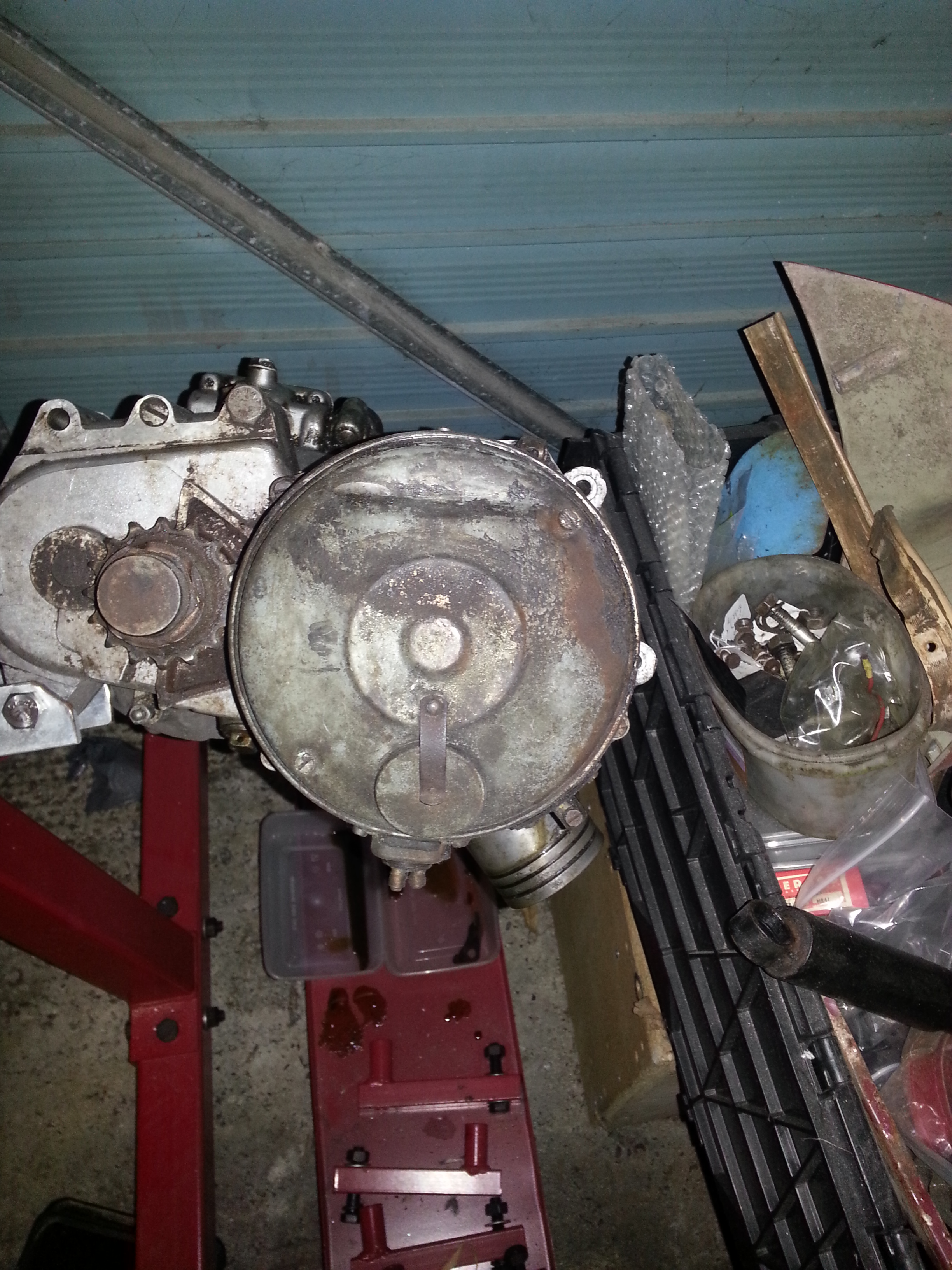
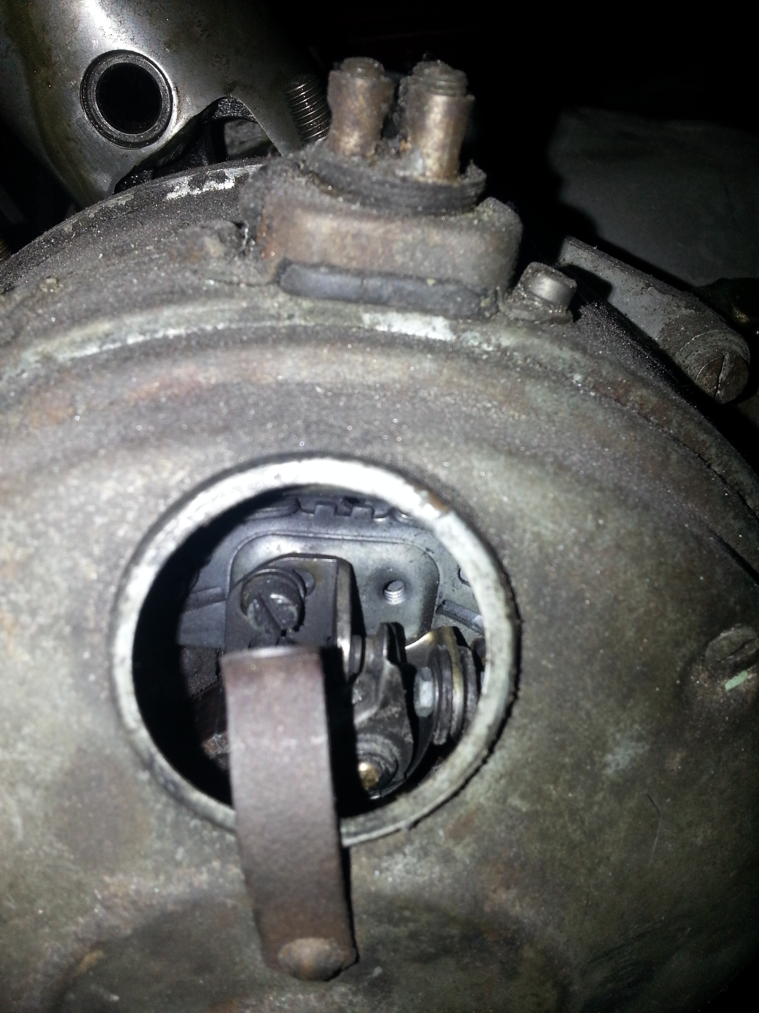
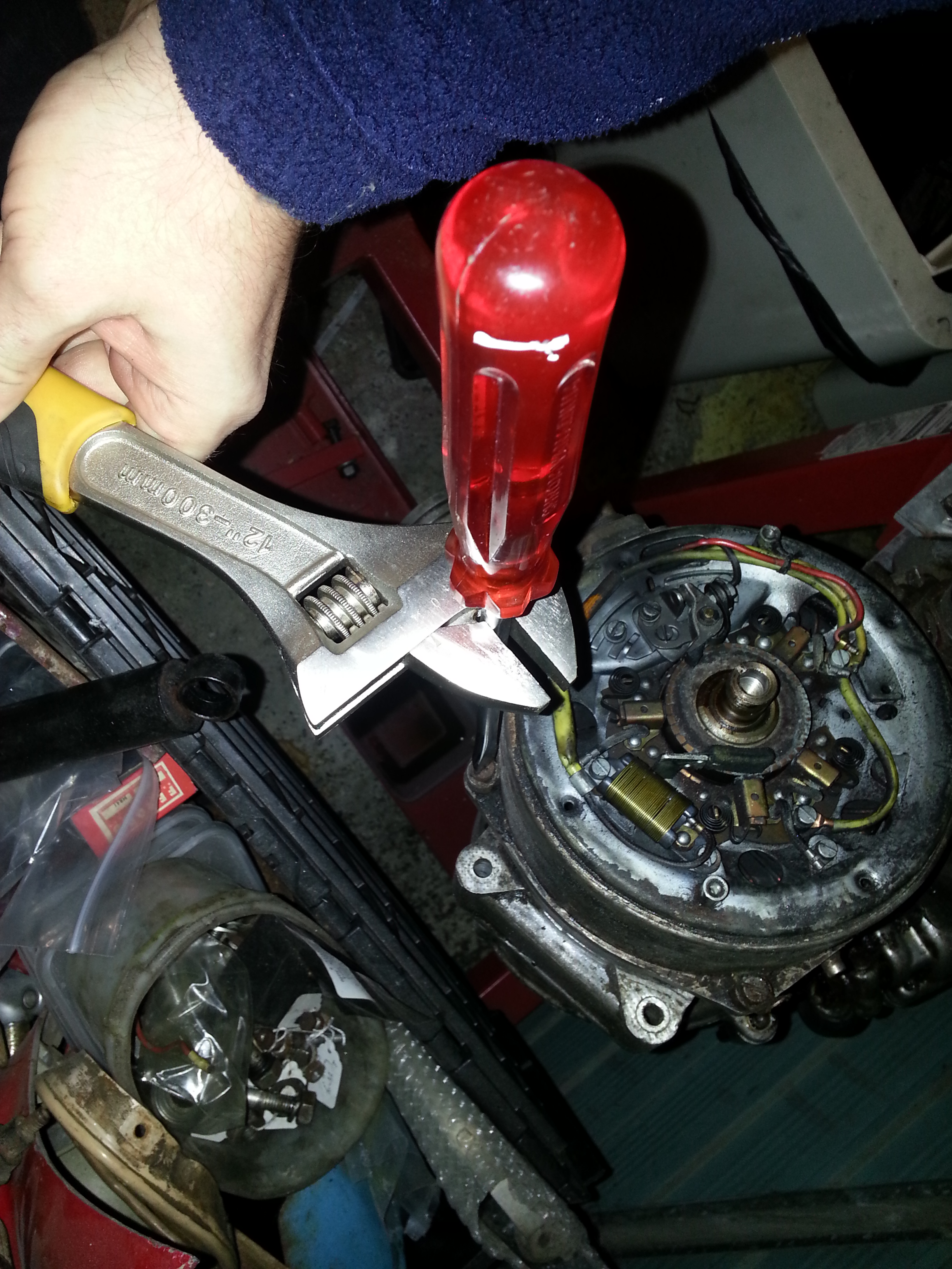
With the cover removed the timing and electricals are visible:
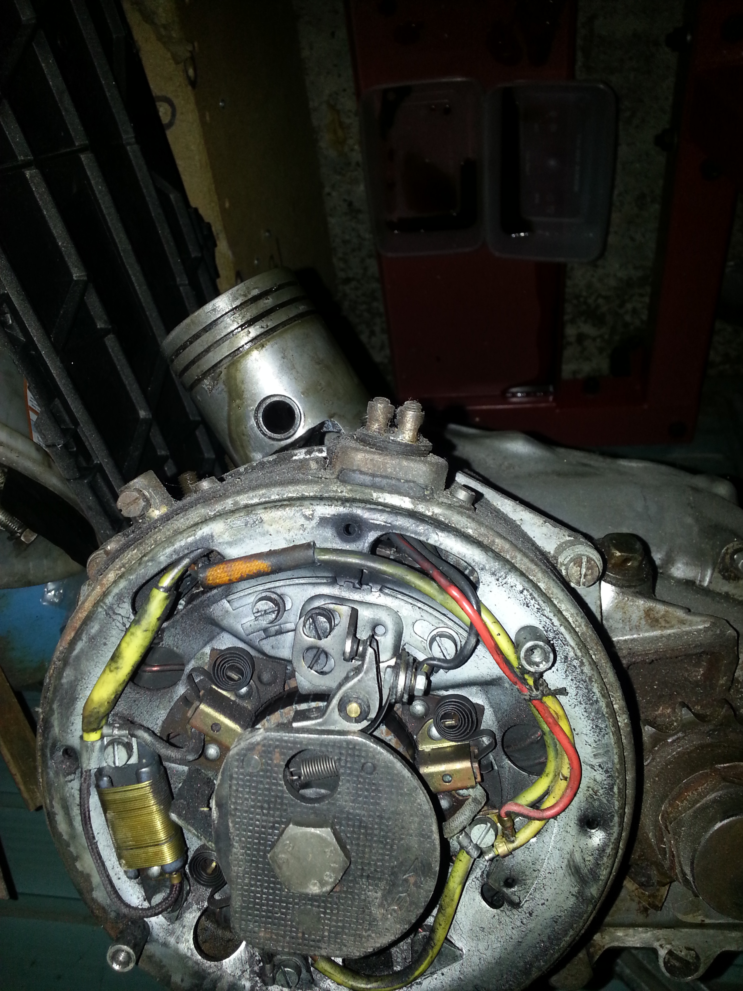
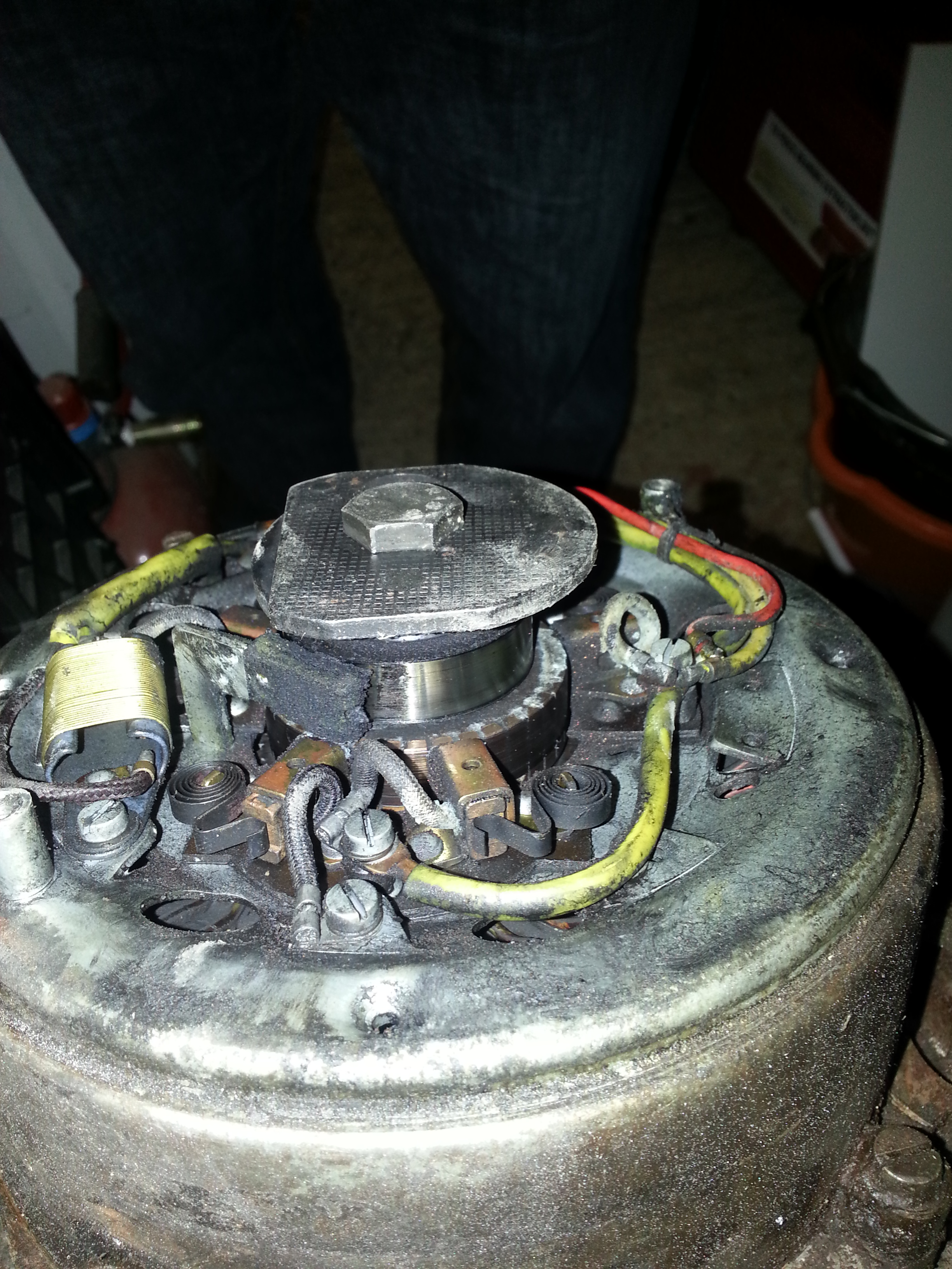
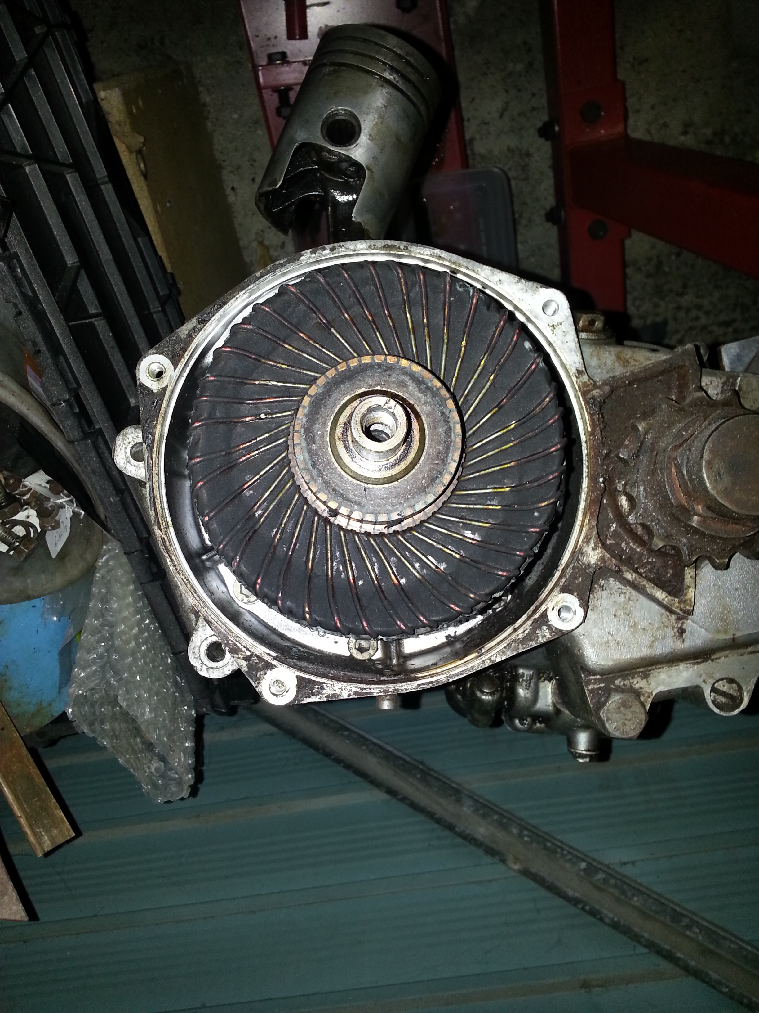
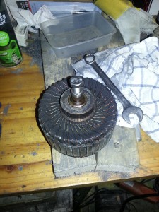
We’ll take the flyball governor off next:
And then the generator:
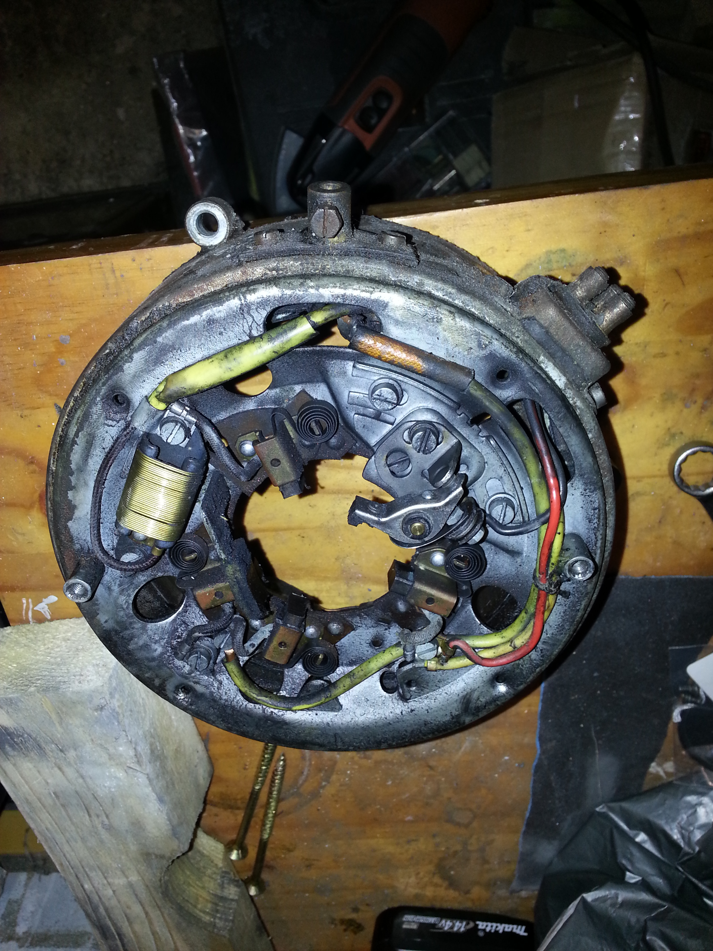
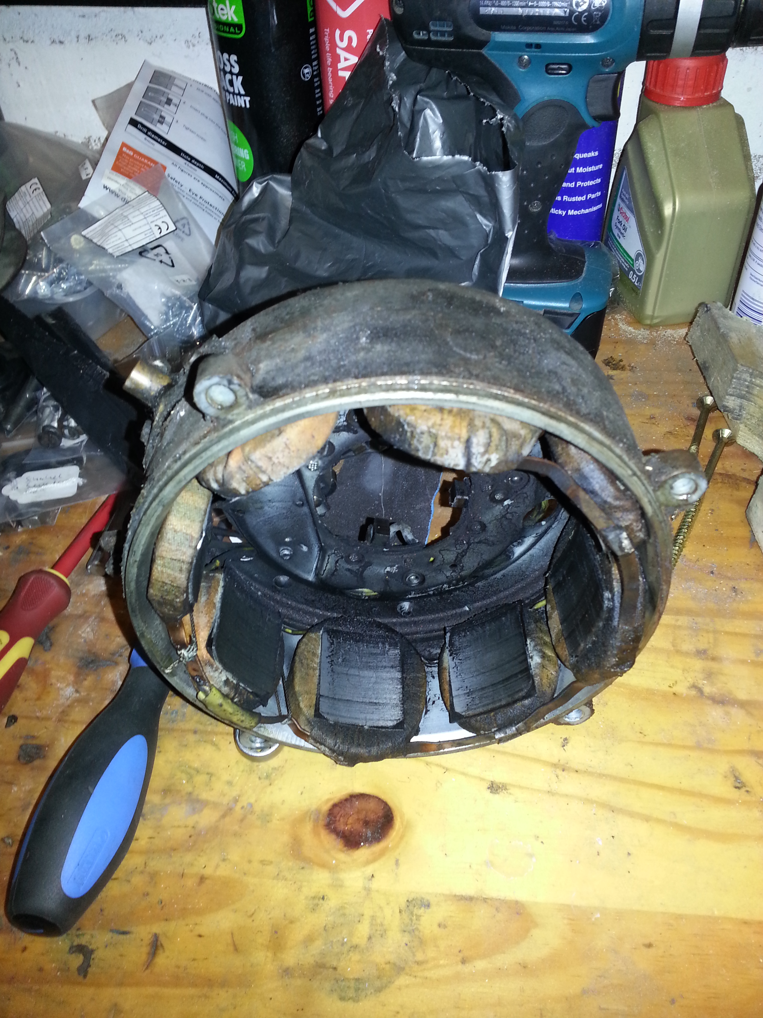
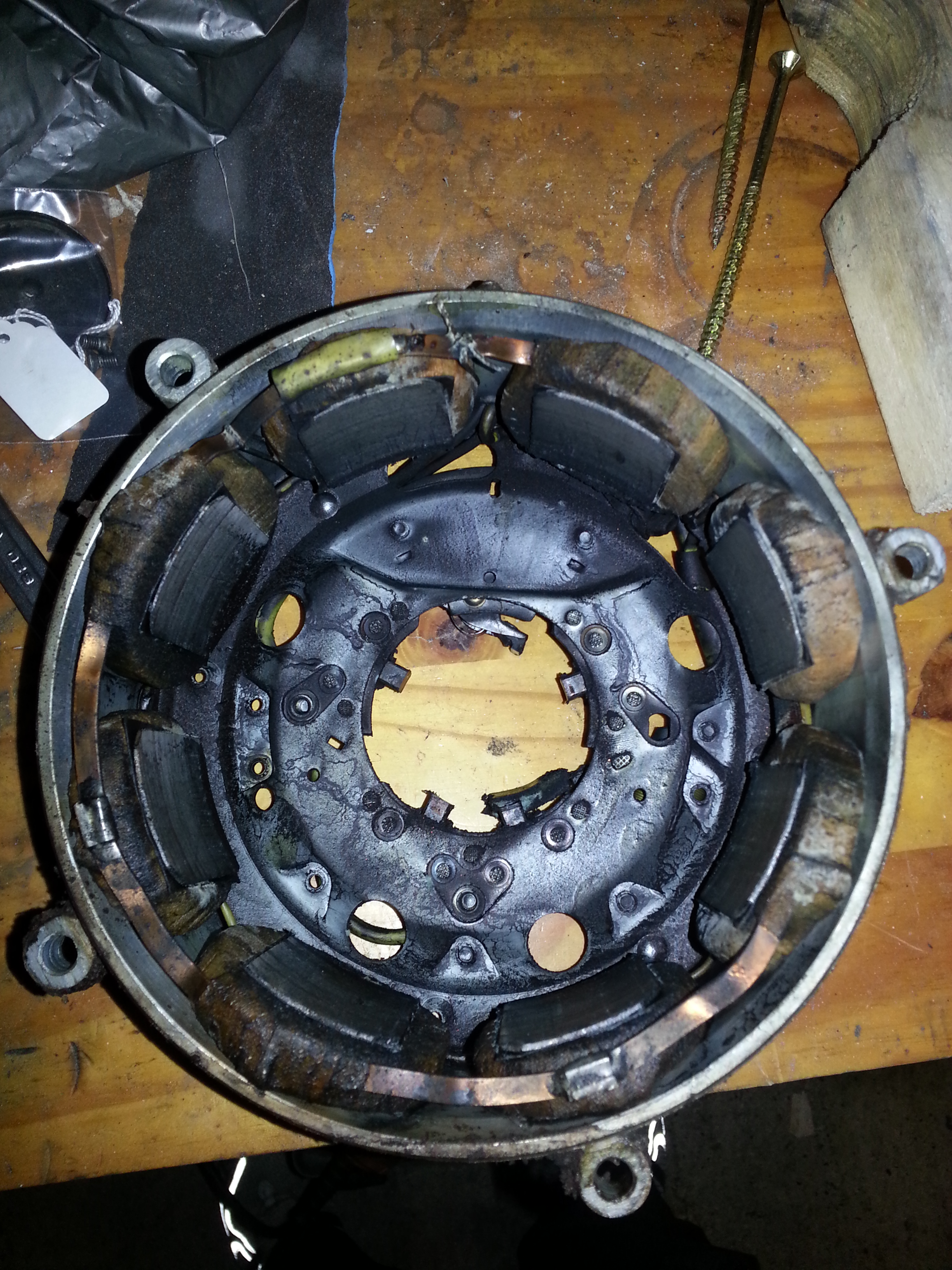
Left is the armature which as you can see will need a very thorough clean given how dirty the contacts are:
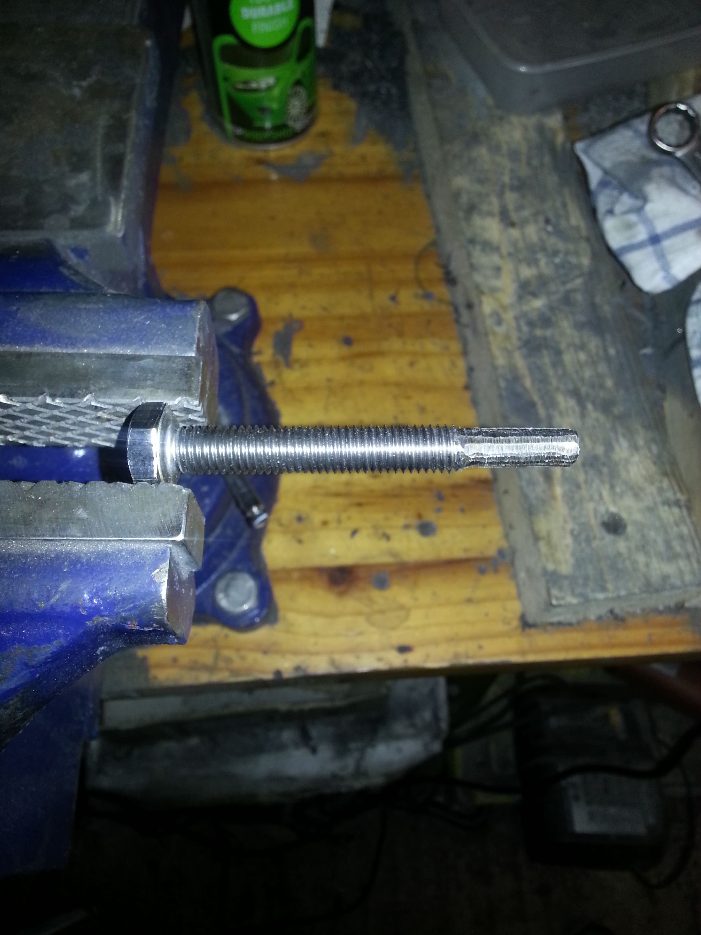
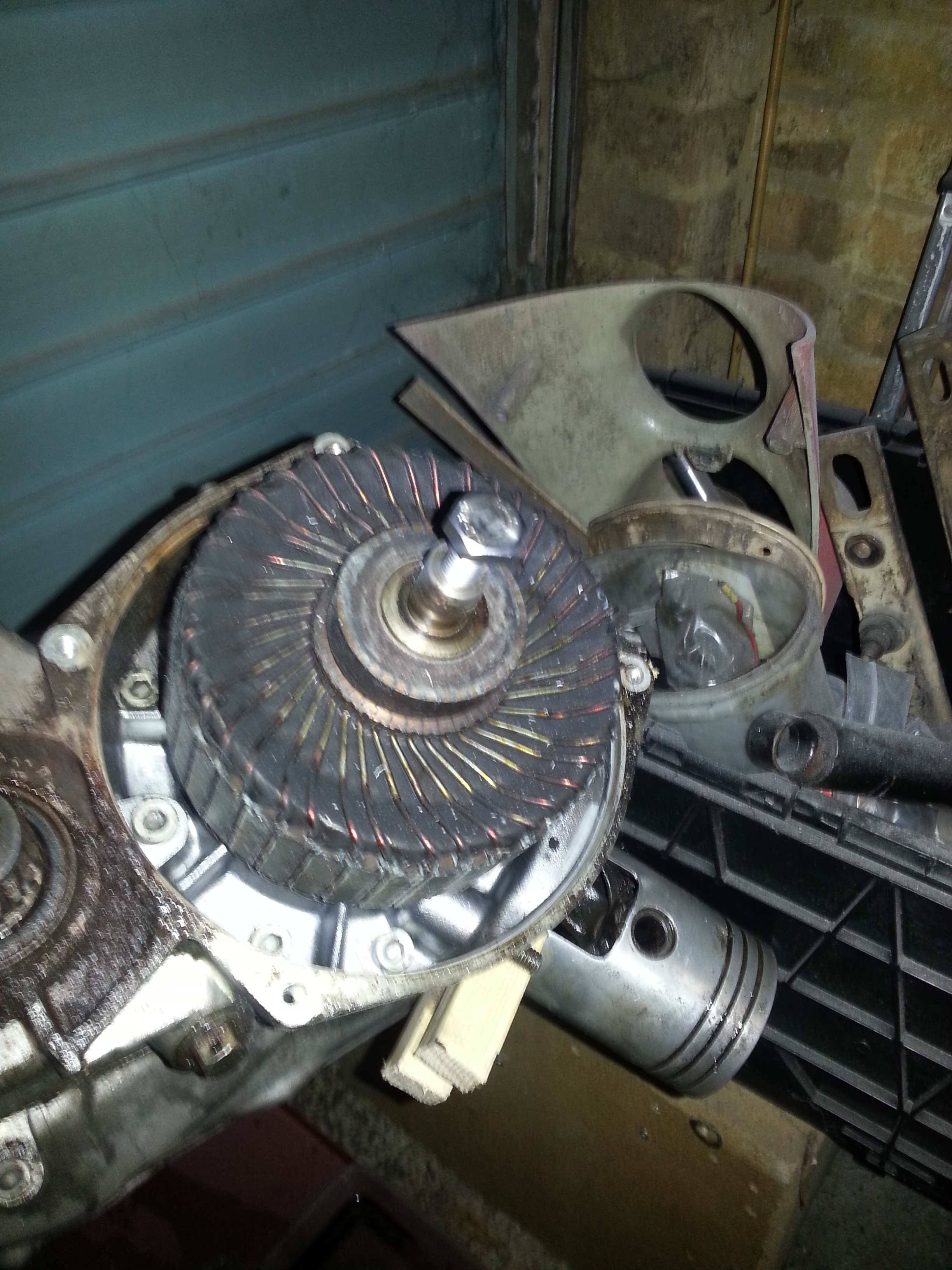
To remove the armature use a push bolt. You can make them by taking an M10 x 80 bolt and grinding off the bottom thread. The top half of the bolt will thread into the armature and the bottom end will push on the crank:
Let’s not forget to carefully take out and store the woodruff key:
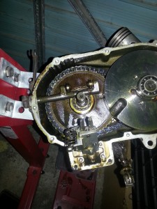
Time to remove the clutch cover but warning, before you do: there are three clutch pins loose in the clutch assembly that are precision manufactured. You will save yourself a lot of trouble if you mark the pin to the right hole. To do so you need to ensure you take the cover off pointing upward:
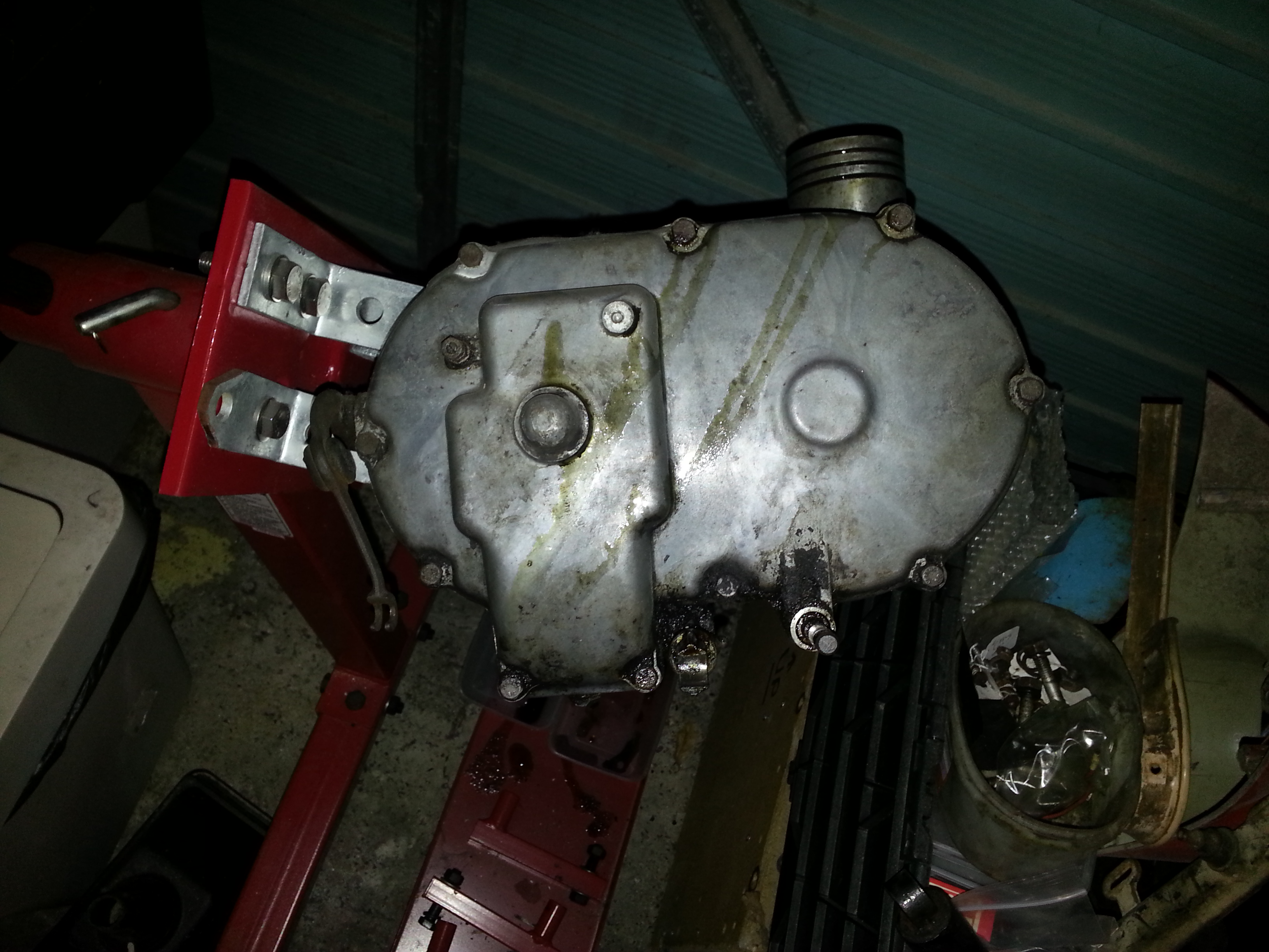
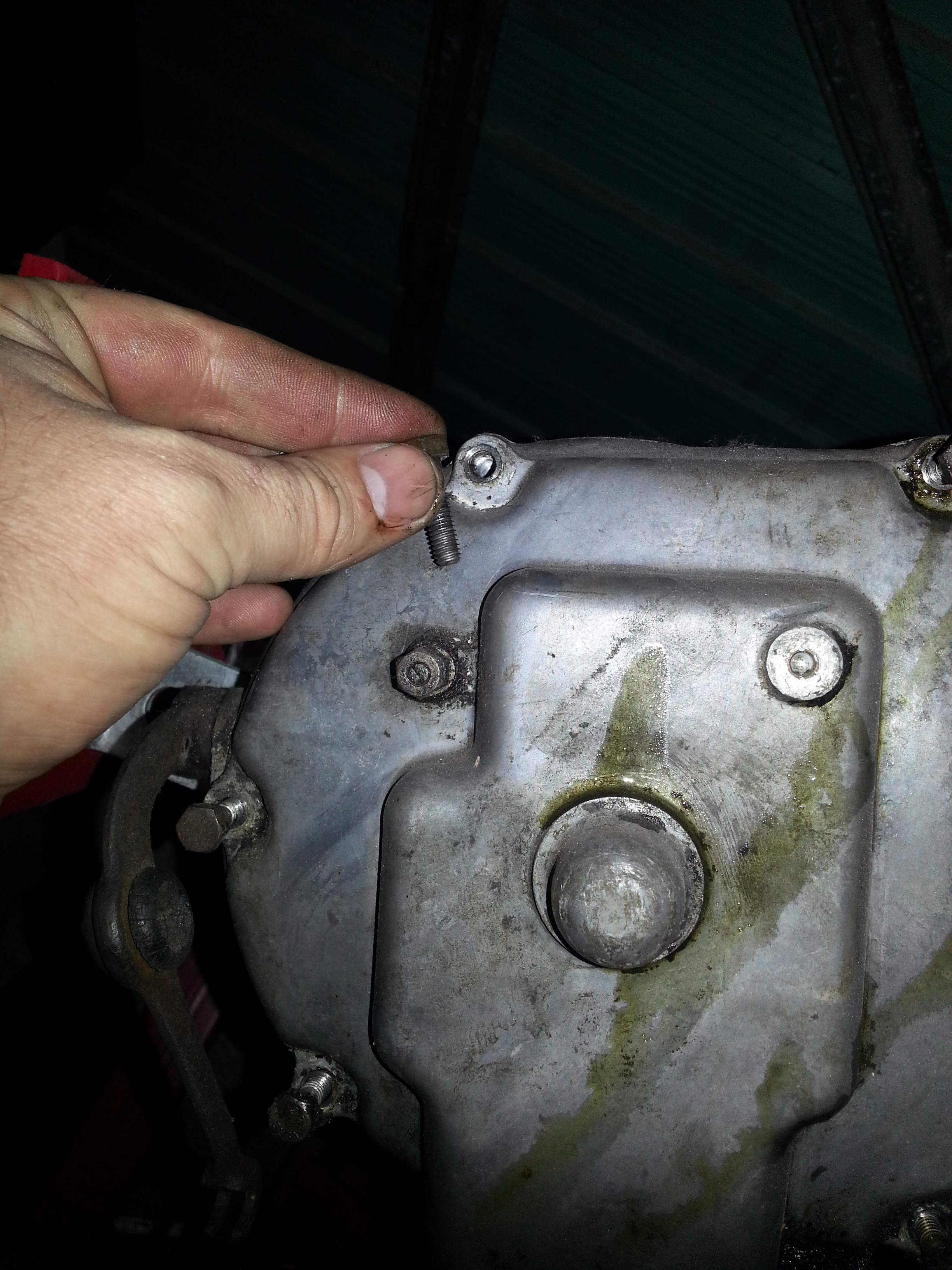
With the cover off you will see the following.
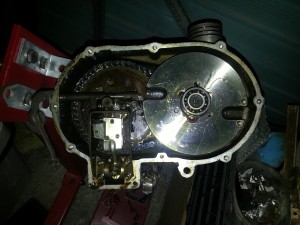
Next step is to line up the clutch bar connected to the clutch arm with the fly wheel. When done you will see this:
I will now skip a few steps as the all important clutch pins are now at risk of falling out. The clutch pins are hidden under a clutch ring.
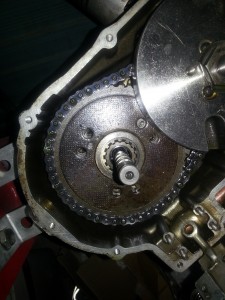
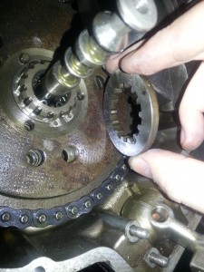
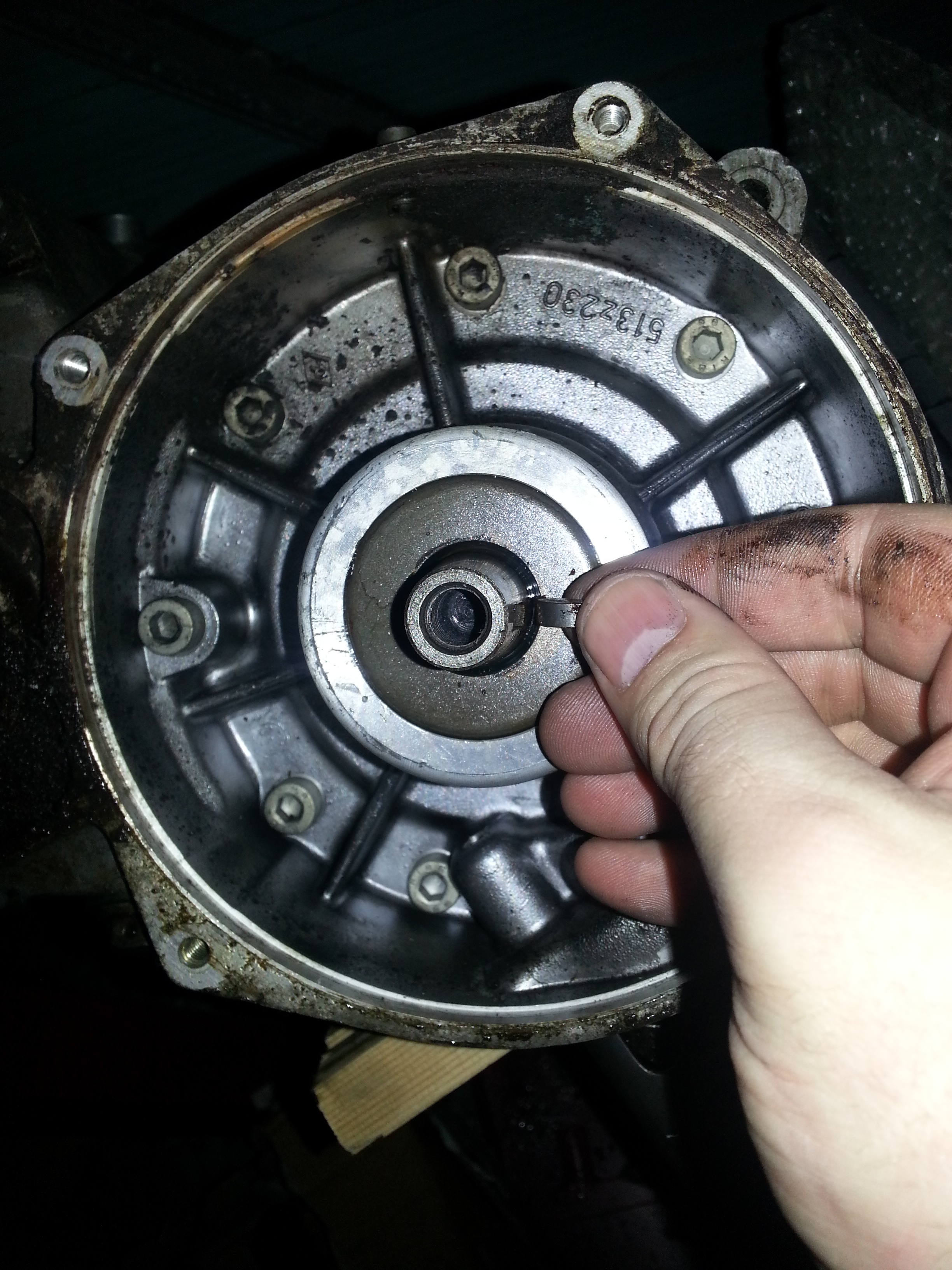
With the clutch ring removed you can see the three clutch pins (I have already removed two, click photo for close-up):
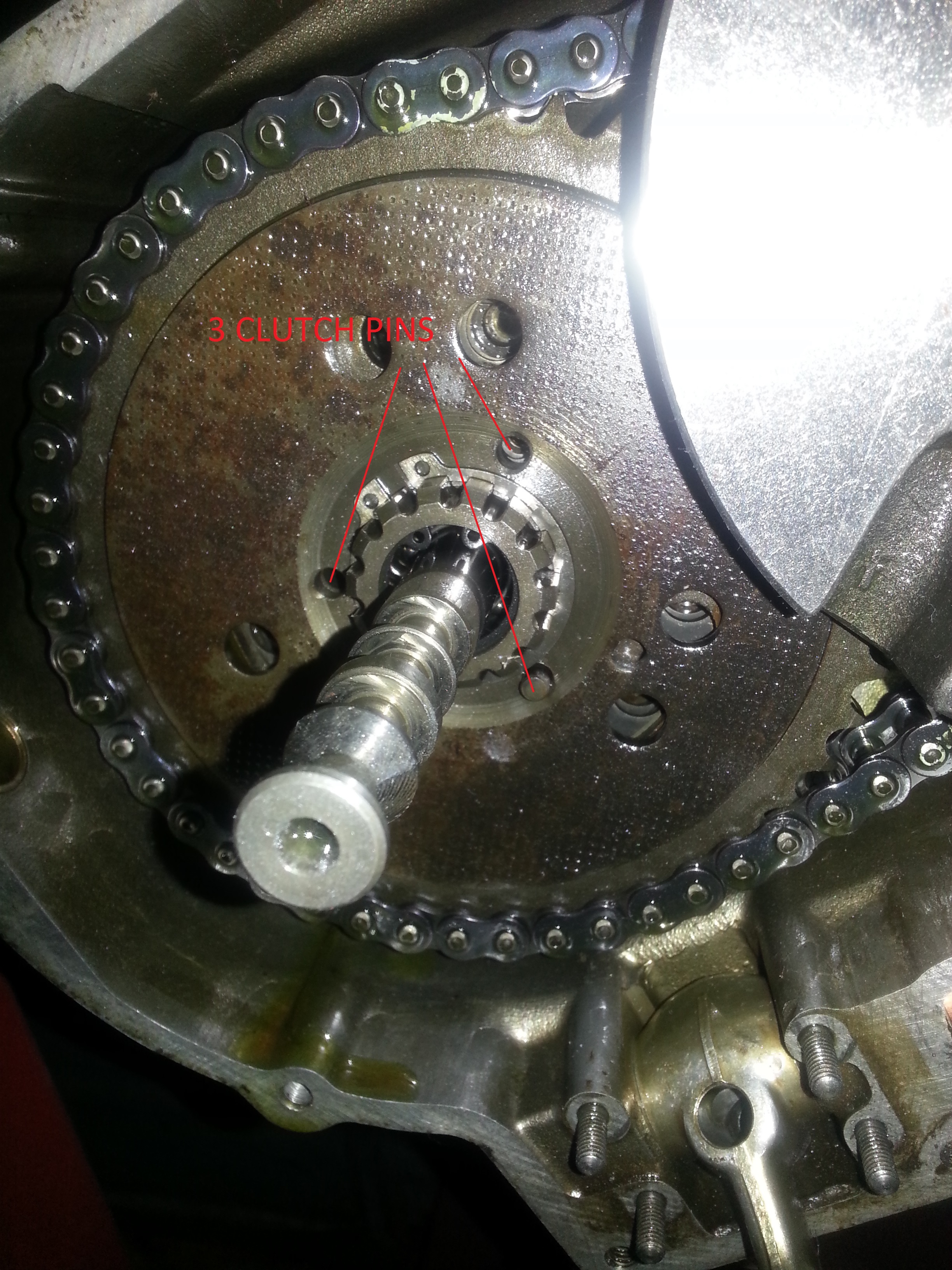
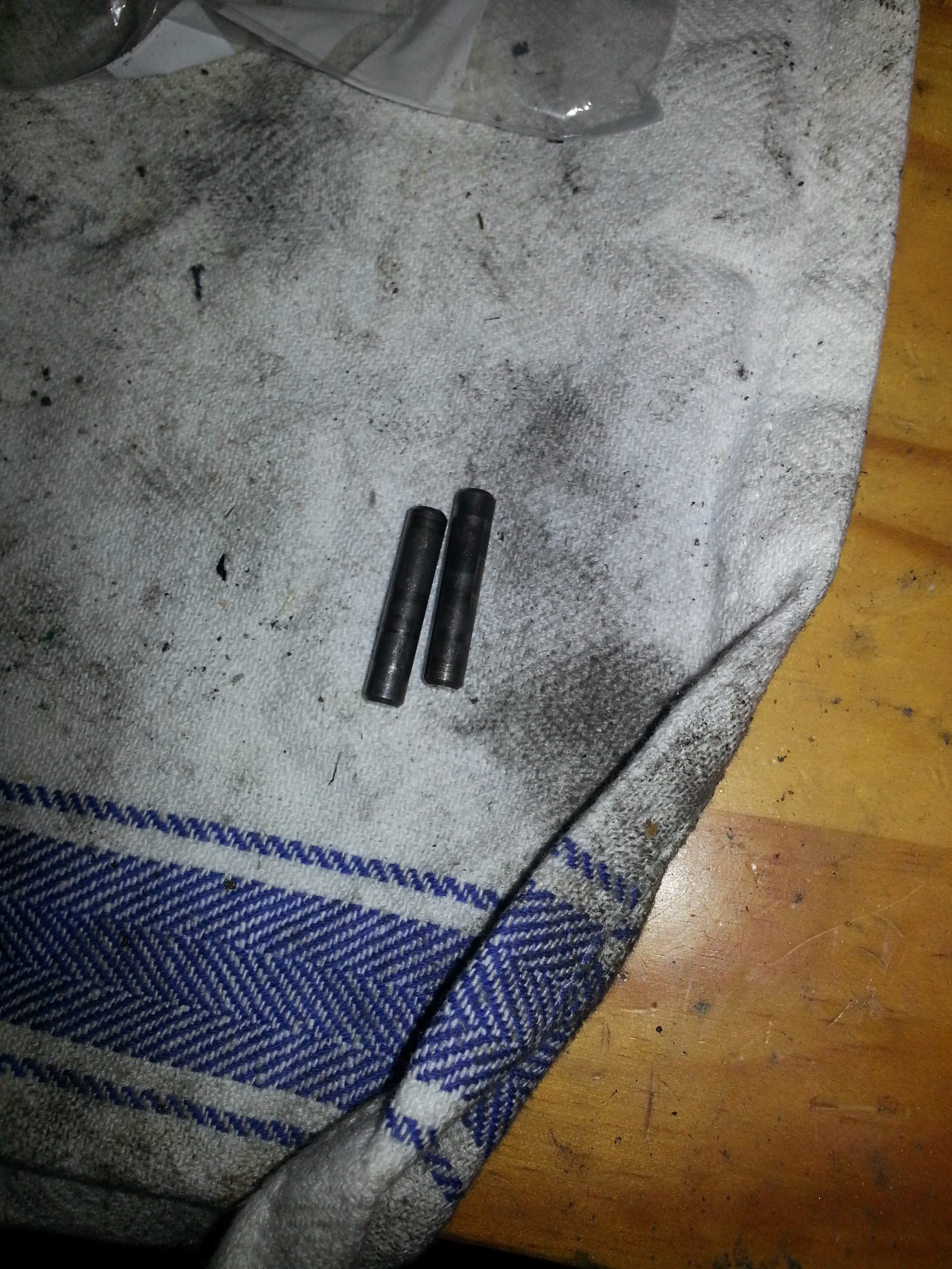
These pins as mentioned above are ground to a very precise size. They ensure that when the clutch ring spins round it remains equidistant from the clutch bar. If the clutch ring isn’t perfectly perpendicular to the drive shaft you will get a rattling sound against the clutch bar and the clutch won’t work silently or effectively.
So please not which pin goes where (mark them and the outer disk) for re-assembly. You will have to measure anyway, but saves time. Reproducing them to the exact size is a pain, so don’t lose them!
Next we take the bearing off the crankshaft:
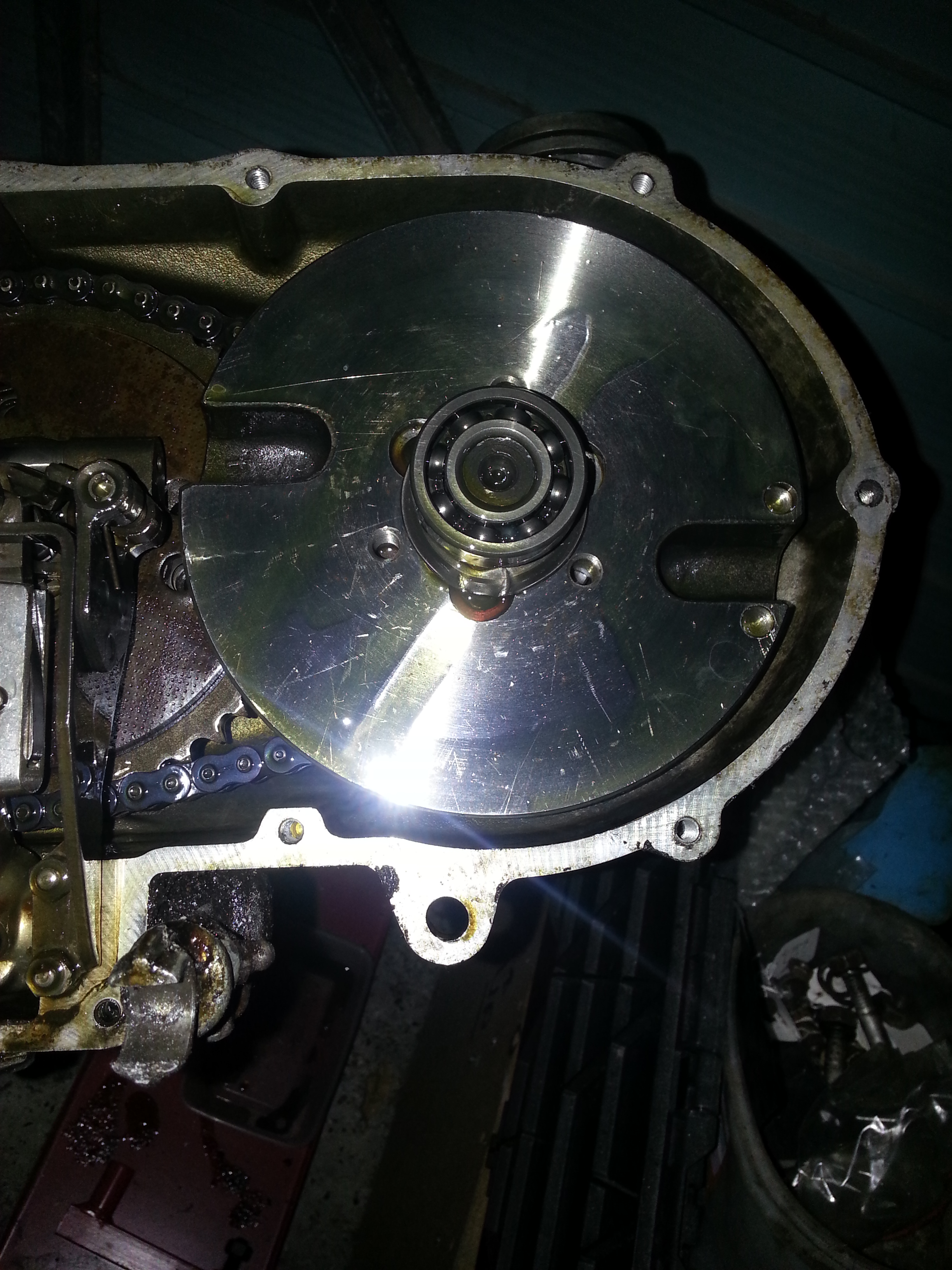
The bearing, a 6203, is loosely fitted into the clutch cover and pops out when removing the cover. It can be removed with a standard bearing puller (it will be ruined by doing so, so don’t re-use it).