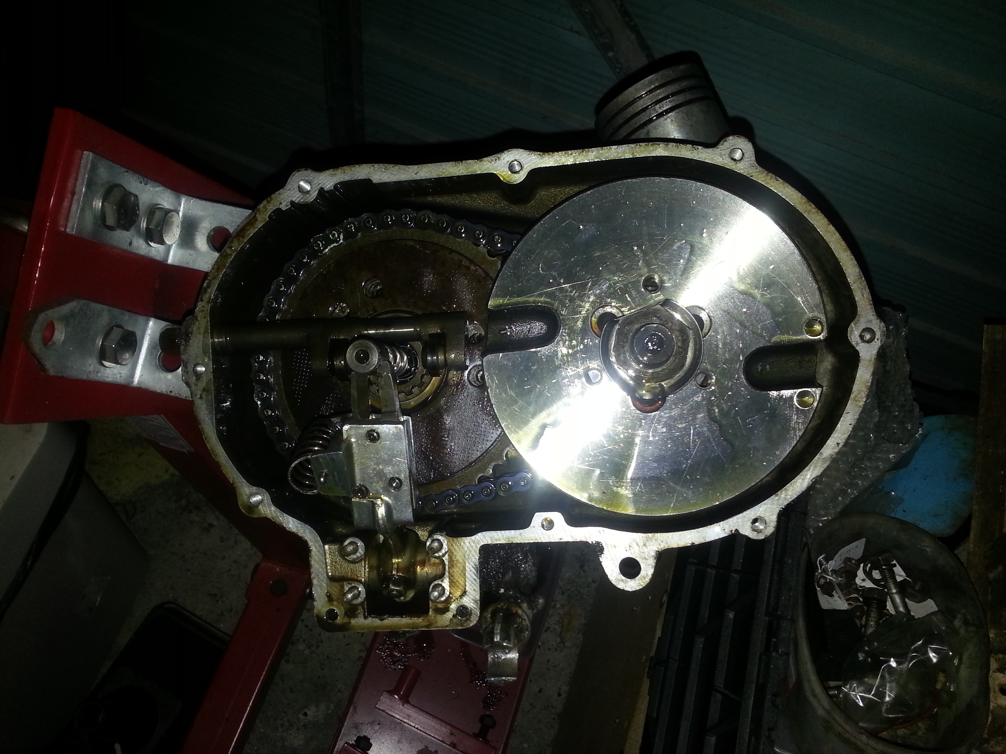
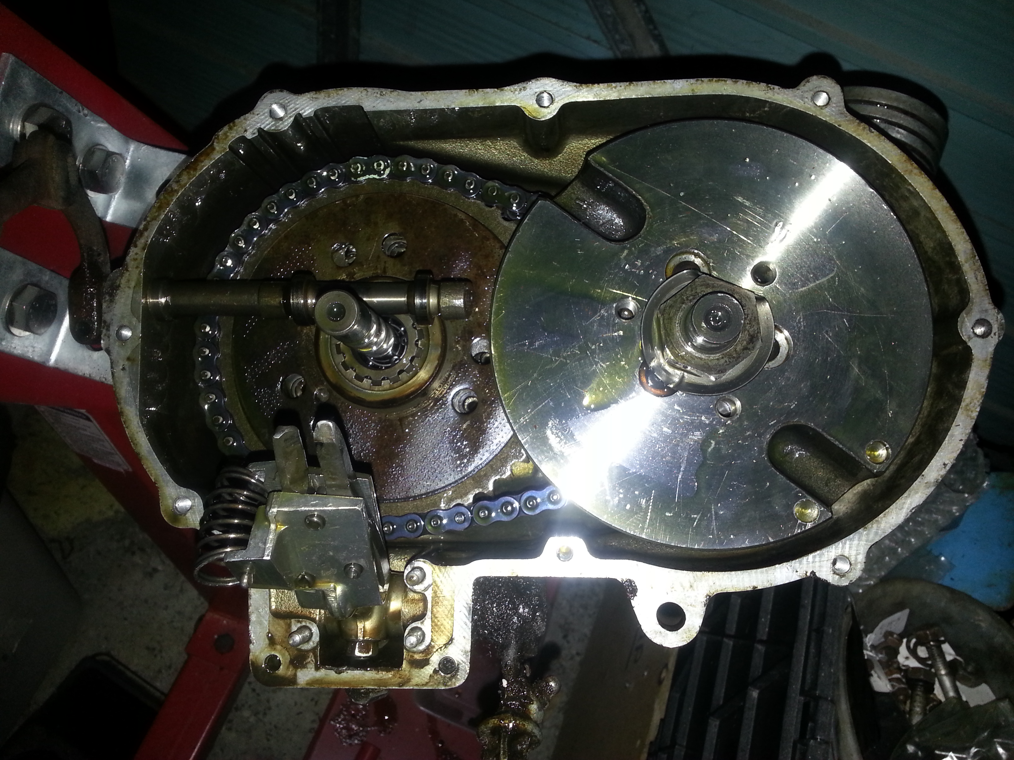
Let’s take a look at the gear shift mechanism:
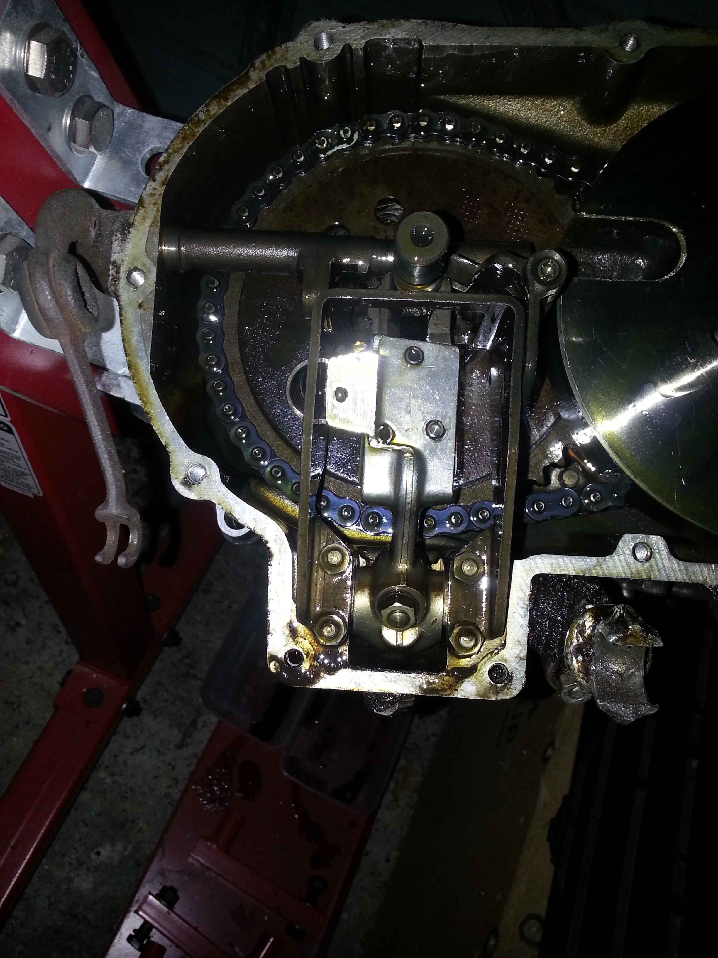
You an see the gear selector fork and the gear selector fork guide. At first glance all looks in good condition. To take a closer look we’ll remove the gear selector fork guide. The distance the guide comes out from the engine have is quite important and you will find distance holders underneath it. Mark carefully which one goes where for re-assembly later:
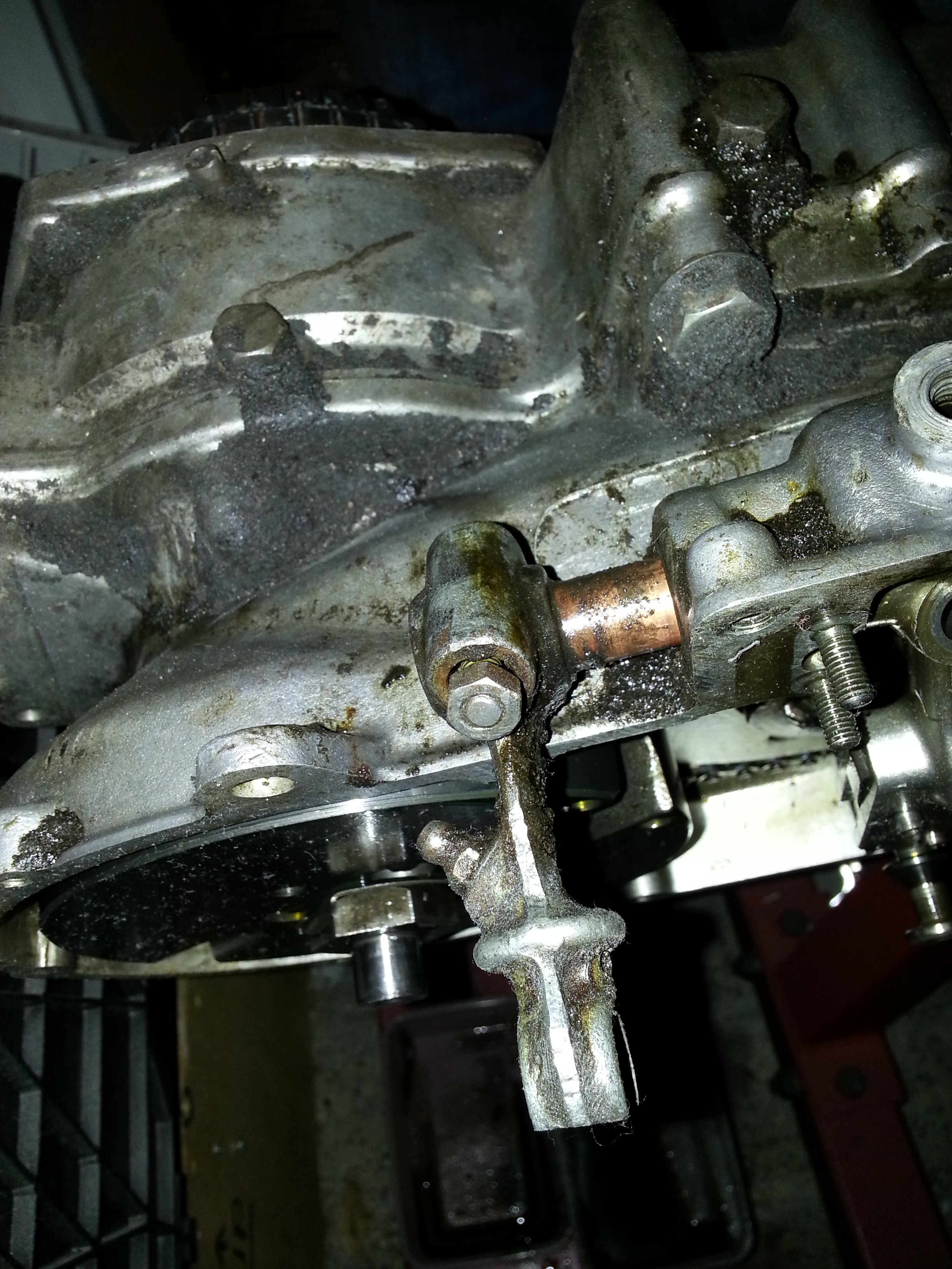
Next we’ll remove the clutch pressure bar that connects to the the clutch lever on the outside. First remove the protective rubber:
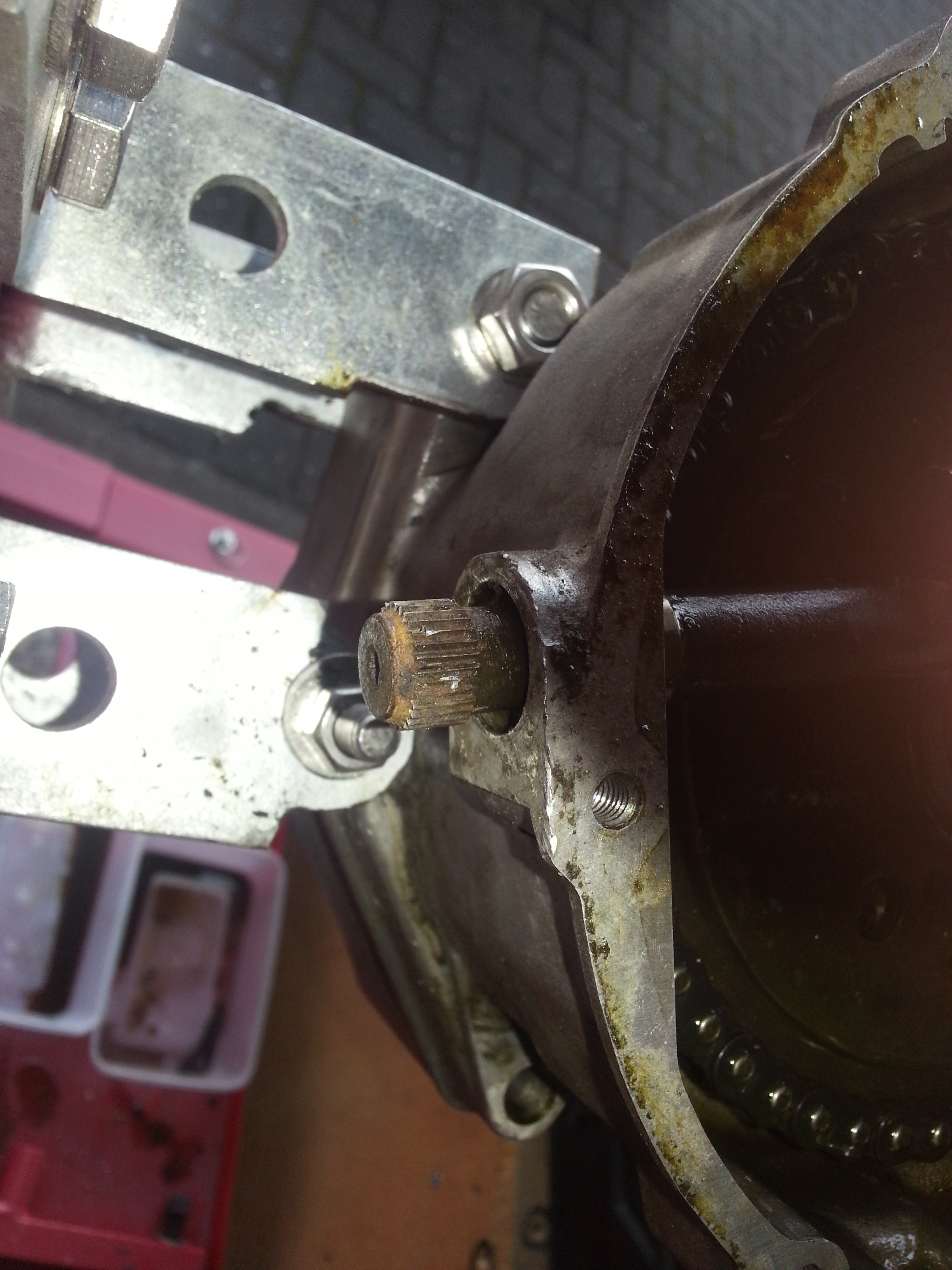
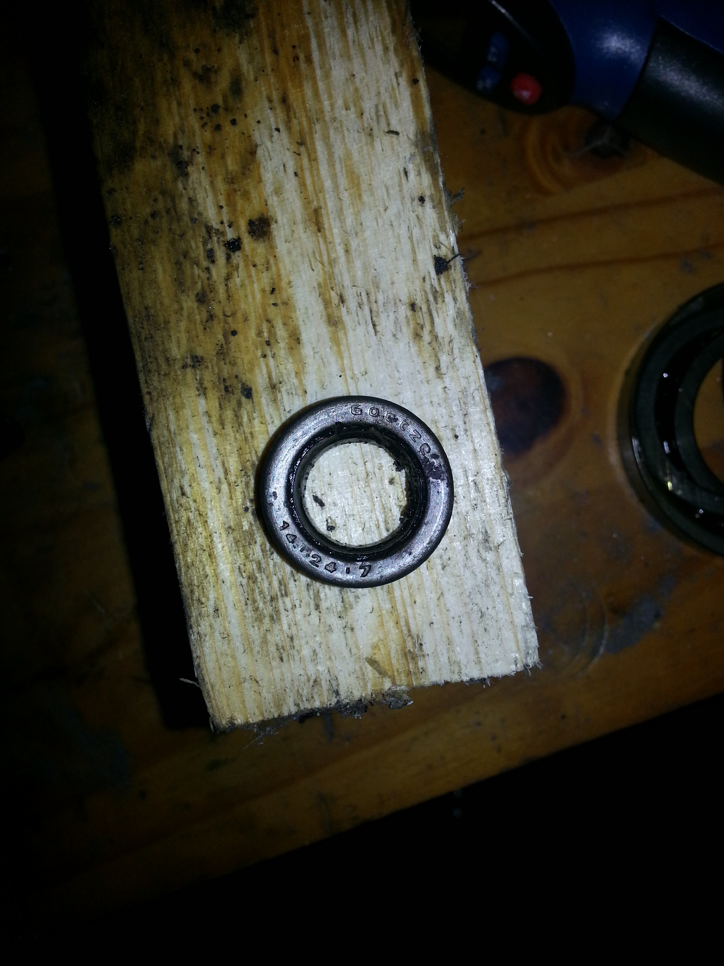
The seal ring is rubber pressed between the clutch and an opening in the housing. Not a very high tech solution, but it does the job. Note the dimensions of the seal ring if yours is still in a reasonable shape. Next, turn the flywheel so it align to the clutch pressure bar and simply push the bar inward for removal:
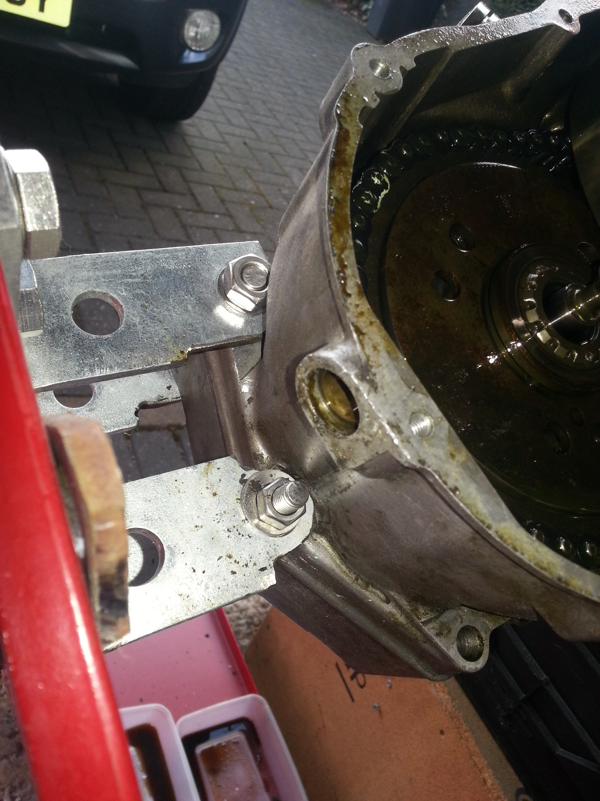
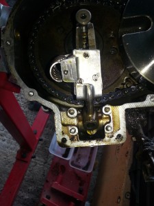
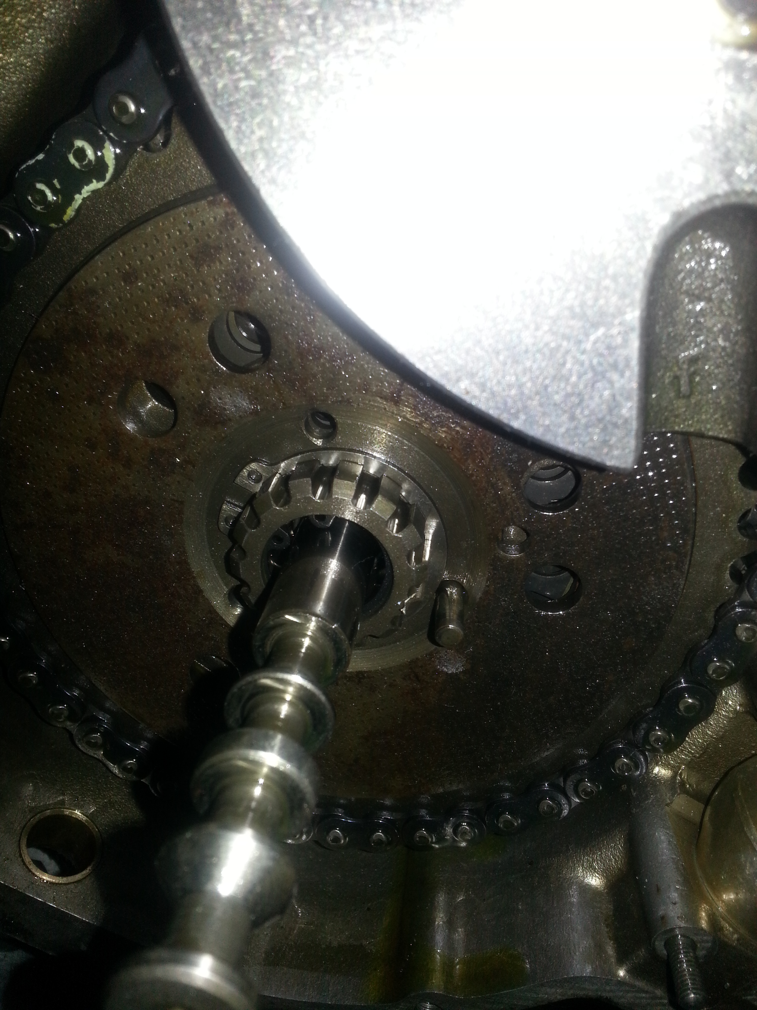
Next we will ‘free’ the gear selector fork by pulling out the gear shaft; you may need to jiggle the flywheel. Be careful, at the end of the gear shaft there are springs and roller ball bearings, so don’t pull it out fully yet; just enough to free the fork up
Note that the clutch pressure bar is still in place in this photo, but the order is not important.
Removing the foot shift shaft at the bottom proved a bit of a challenge for me.
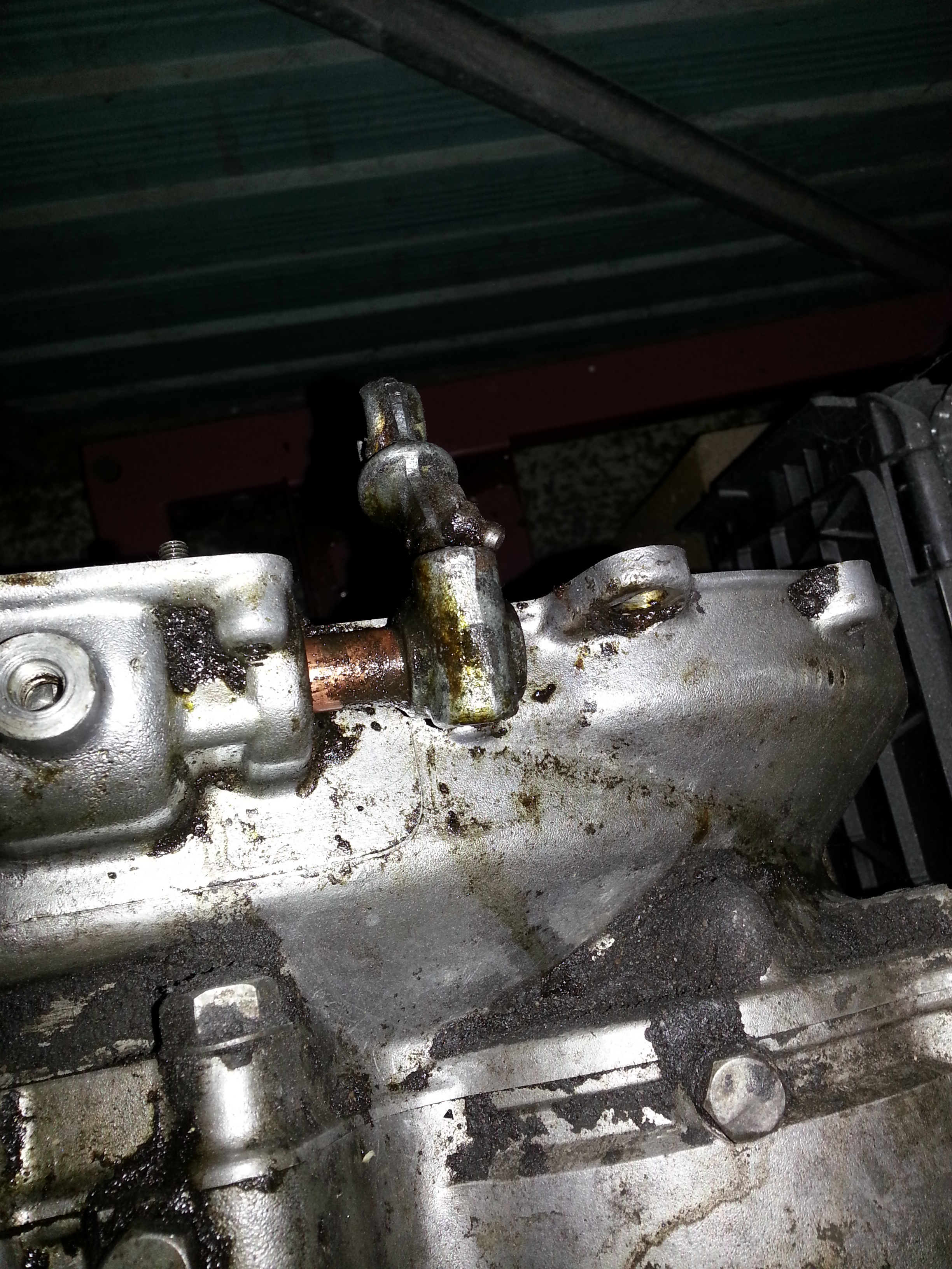
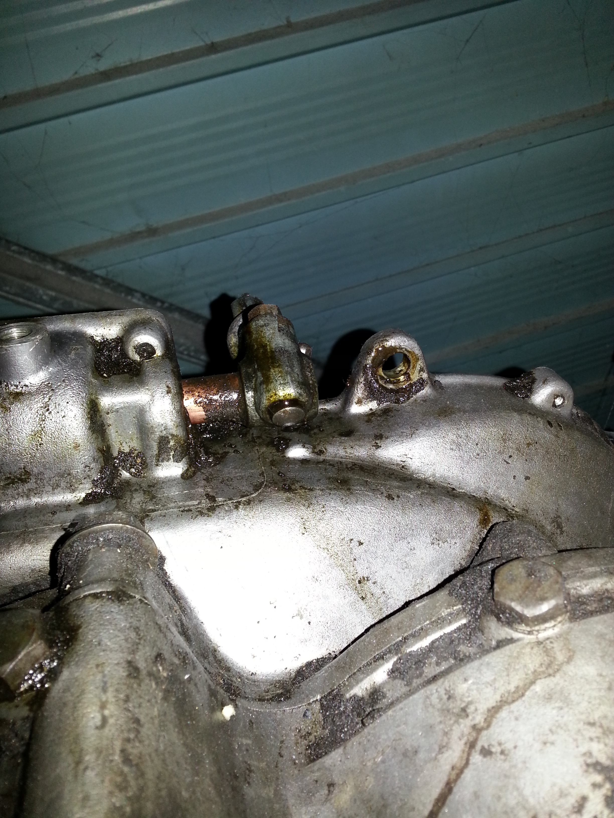
First I went too rough on the outside cotter pin holding the gear shift lever in place and bent it by hammering on it with the nut opened a few turns. As this is a quite delicate installation, not the way to go… I ordered a cotter pin press from bikesmithdesign.com (65 USD…). After removing the inner cotter pin (this one went out with a gentle tap of a nylon hammer) the shift shaft comes out enough to apply the cotter pin press:
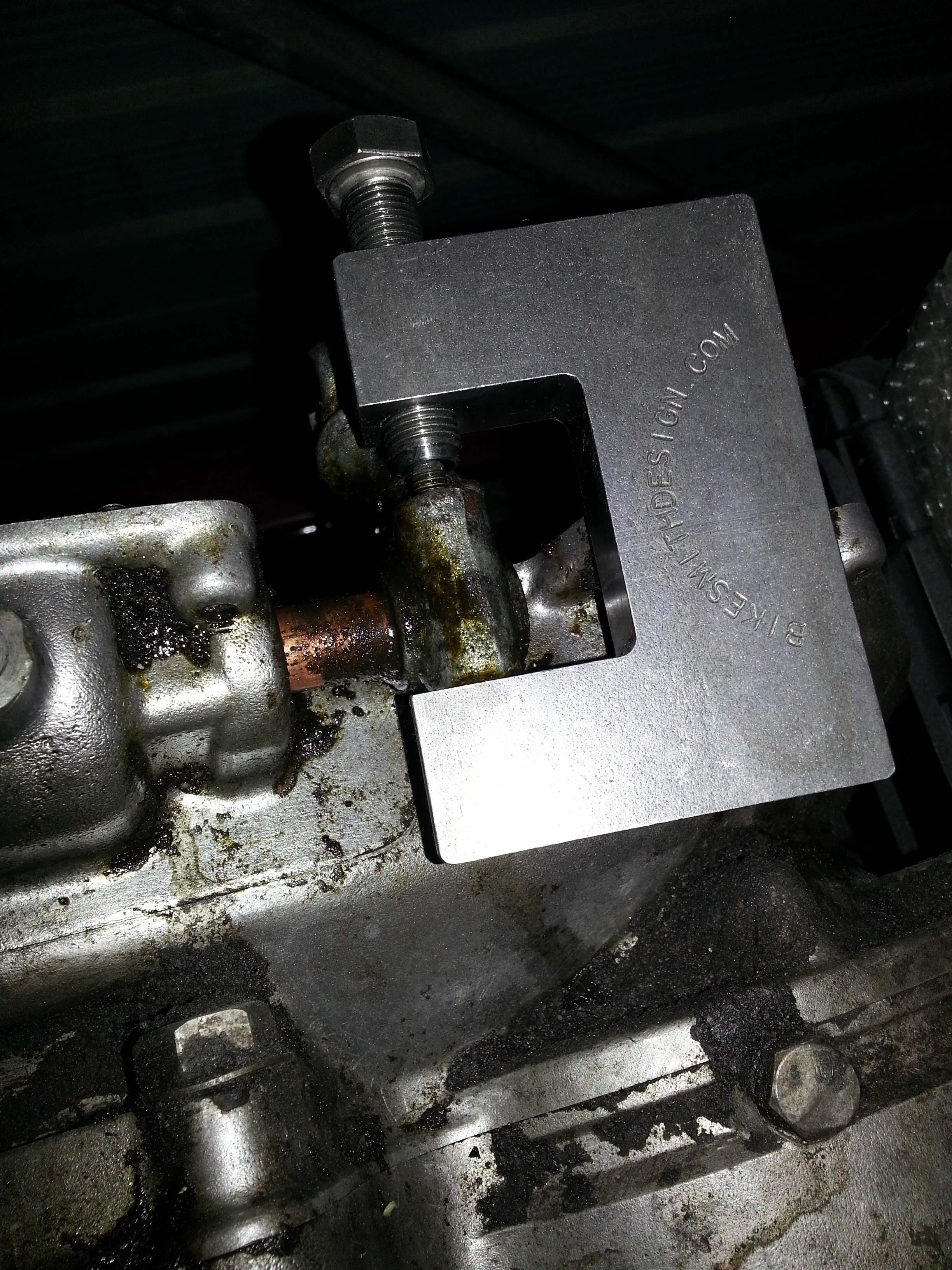
No matter how rusted shut, this will do the job easily and without damage.
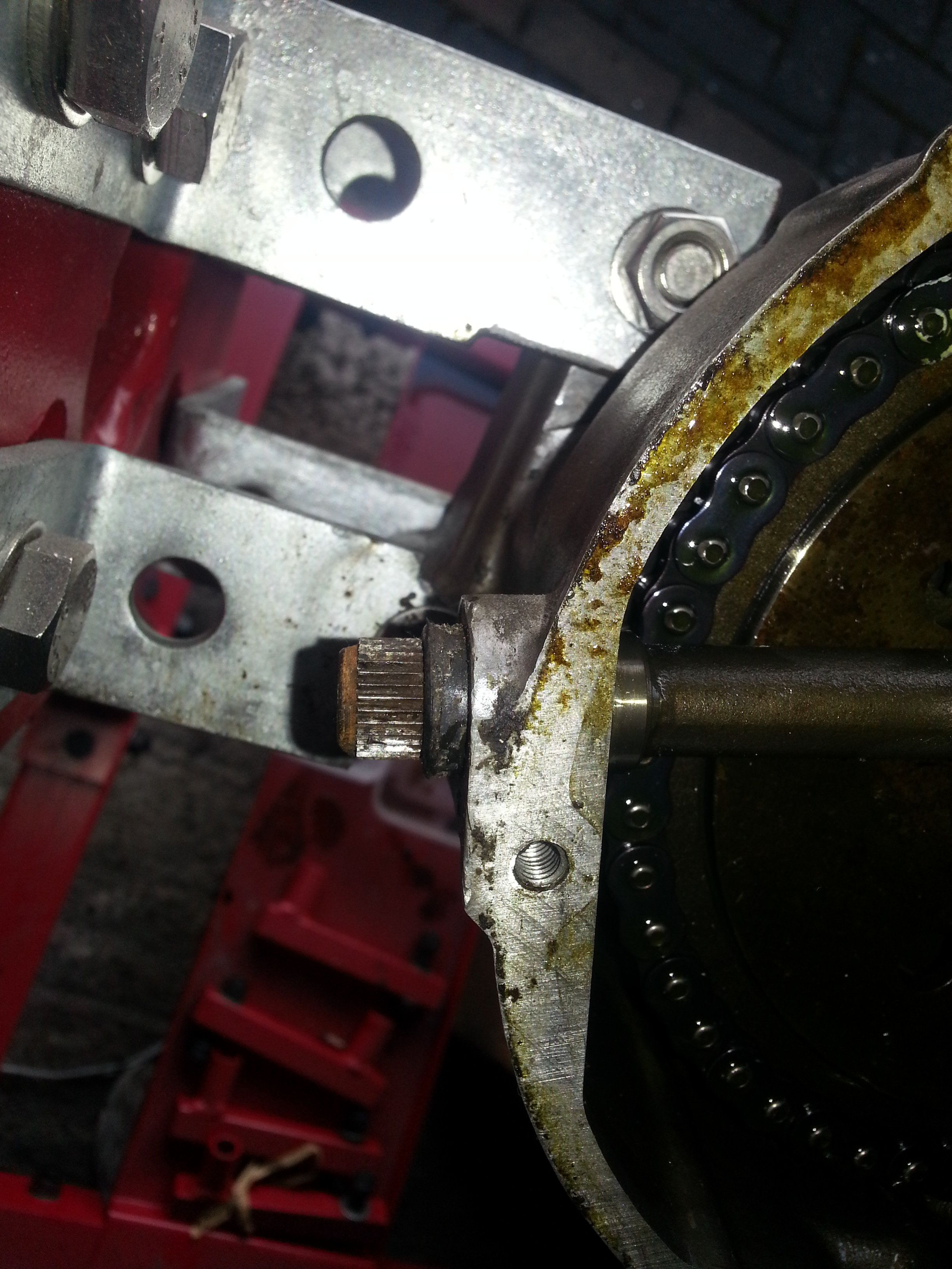
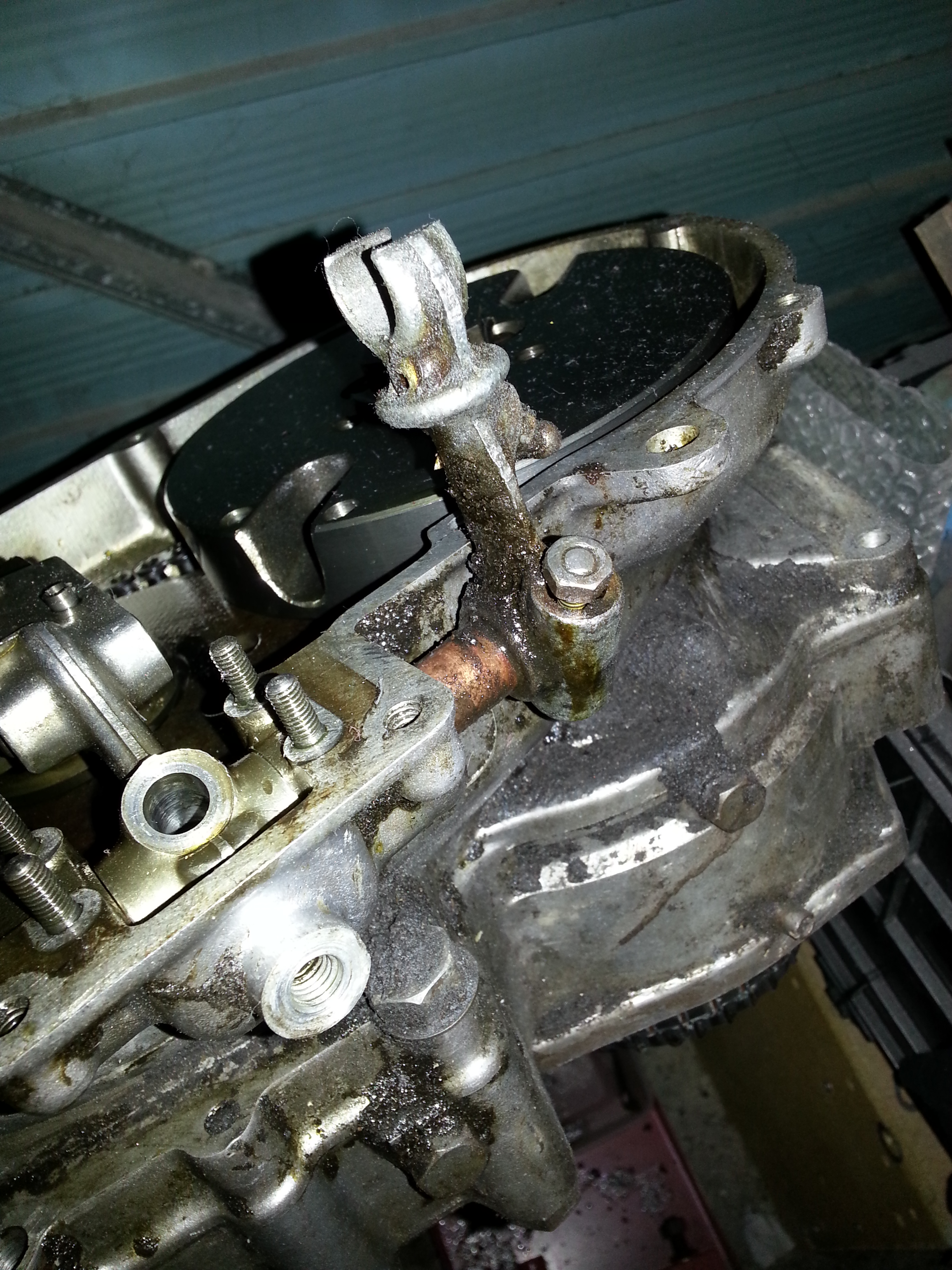
Taking off the gear shift lever itself is a whole other challenge. There is a protrusion on the engine half that makes easy removal impossible. After much thinking I ordered and cannibalised a 10 GBP windshield wiper puller that does the job perfectly if you grind off a bit of one of the legs so it fits in between the shaft and the engine half:
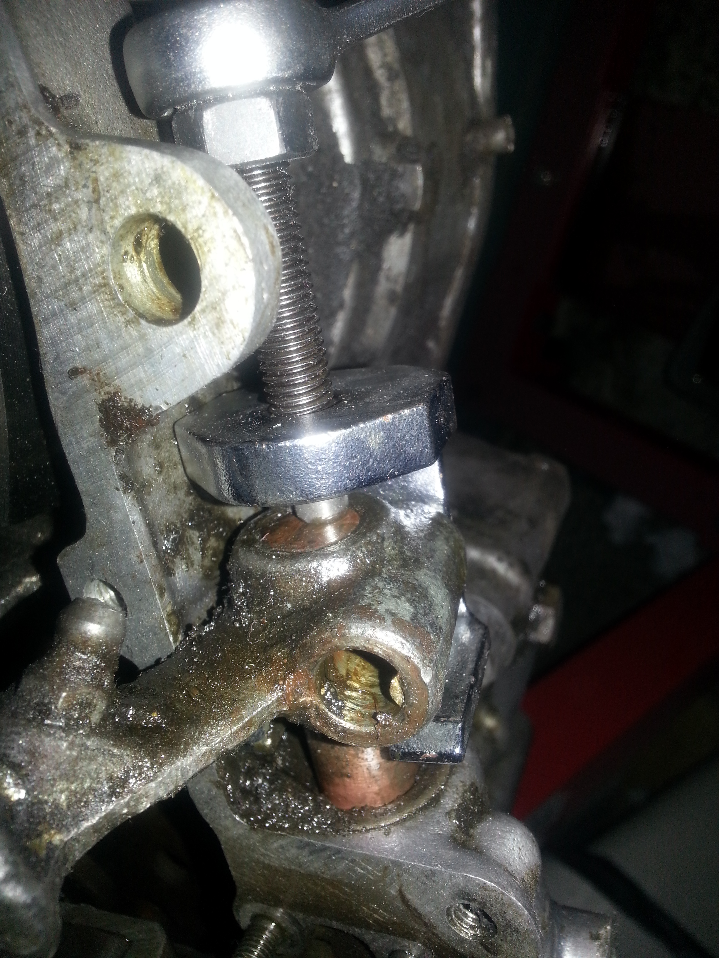
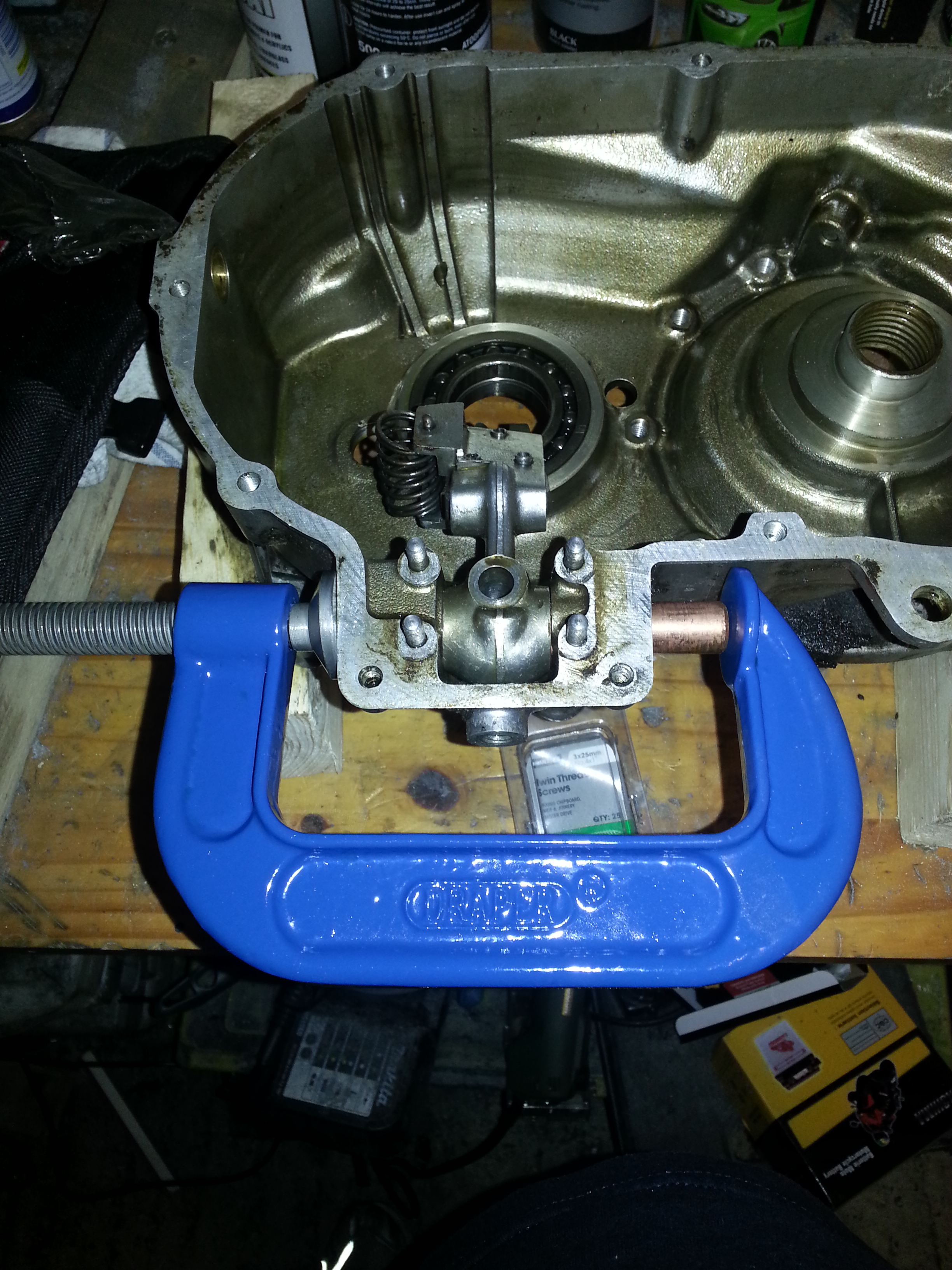
It’s a tight fit, but does the job perfectly and without damaging anything which is quite key with a copper shaft. The shaft itself needs to be removed through the other side of the engine by pressing it through. There is a blanking plate installed which will come out without issue. The same protrusion prevents it from being removed normally. This appears to be a bit of a design flaw in my opinion:
You will need a C-clamp and various washers and socket wrench sockets to press the pin out. Here’s how you start and you can see the blanking plate coming out:
Not that I didn’t do all of this in sequence as I had to figure out how to remove parts and order the right tools in between, but this is a logical sequence if you need to remove these parts.
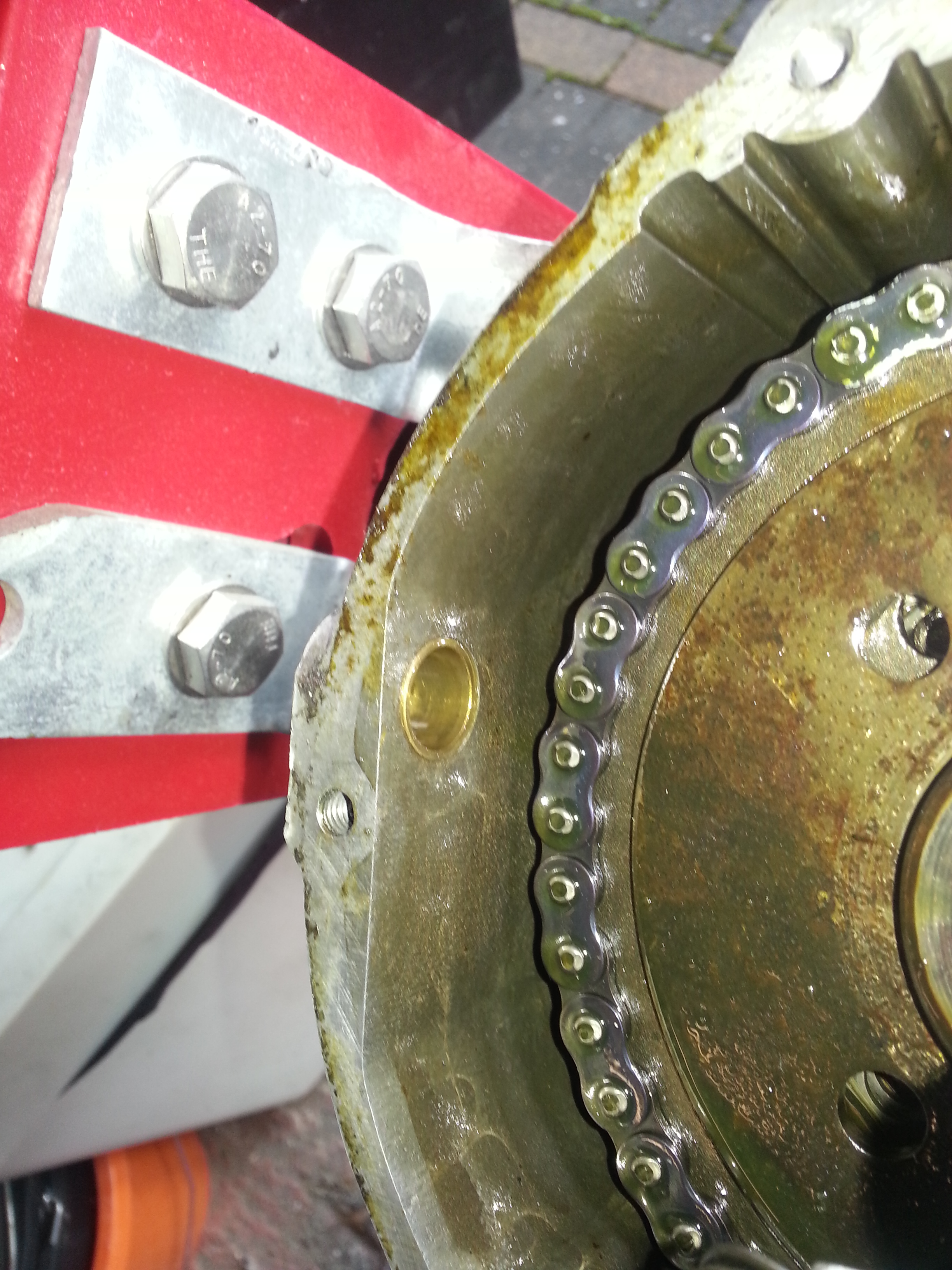
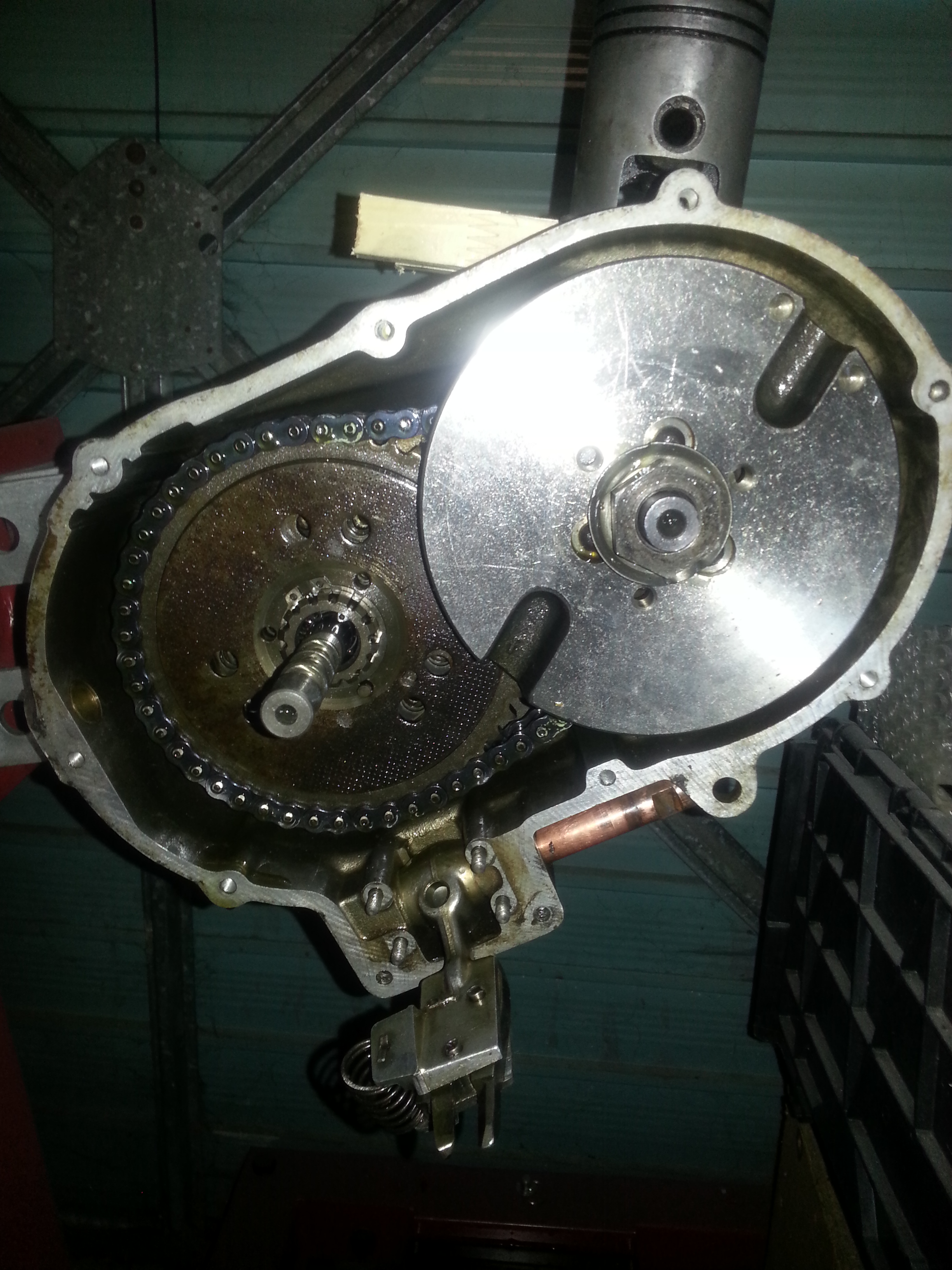
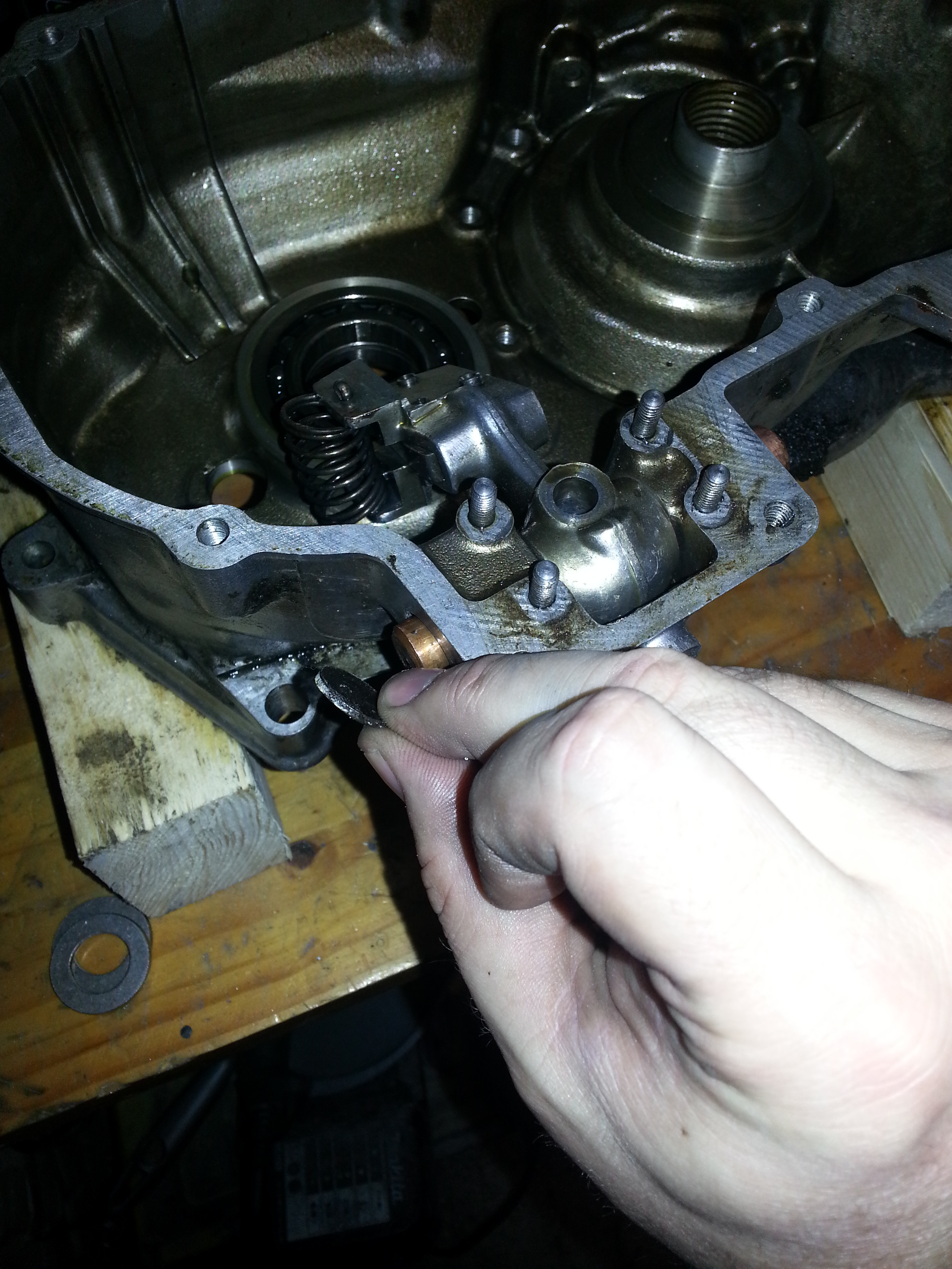
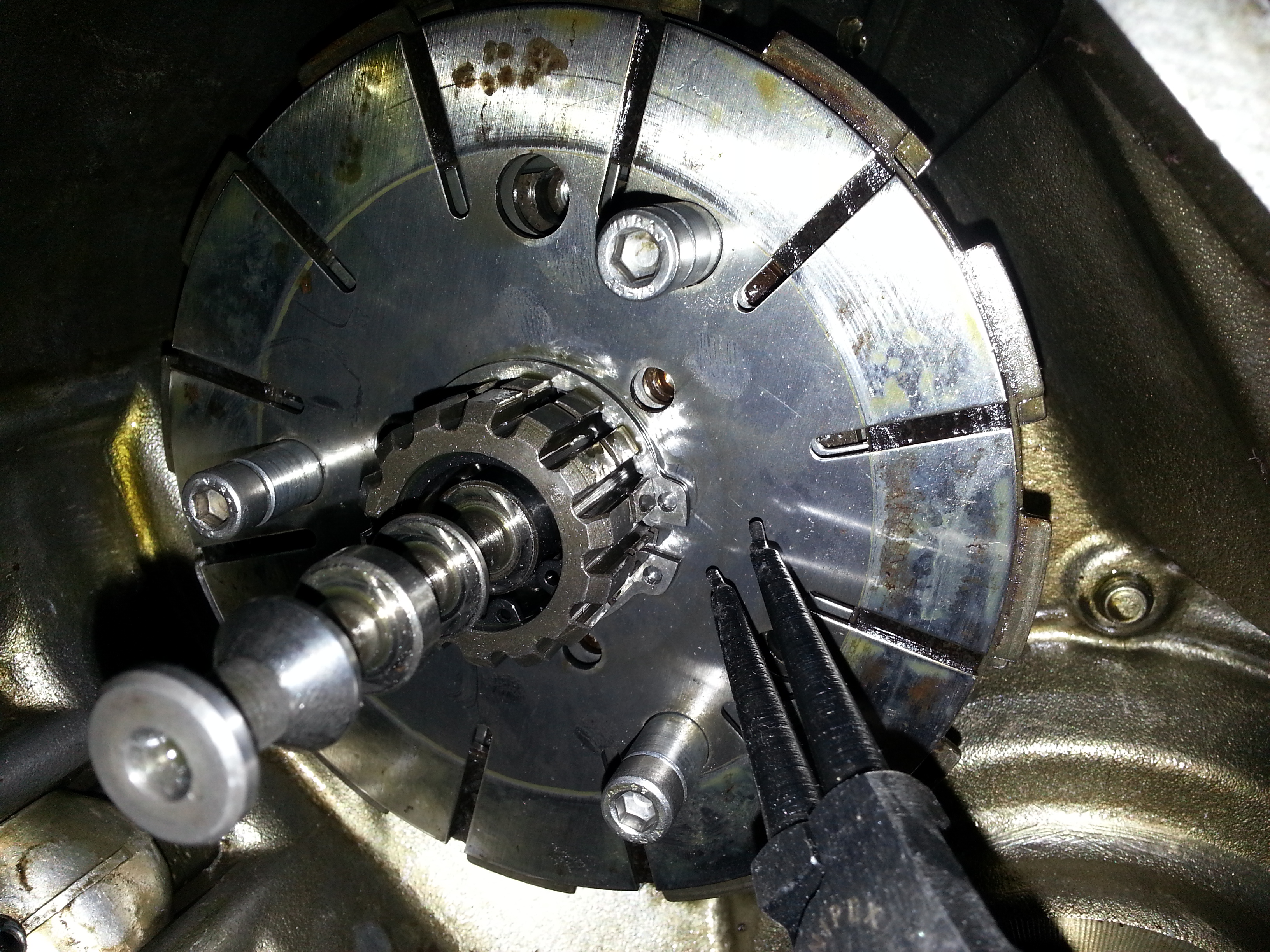
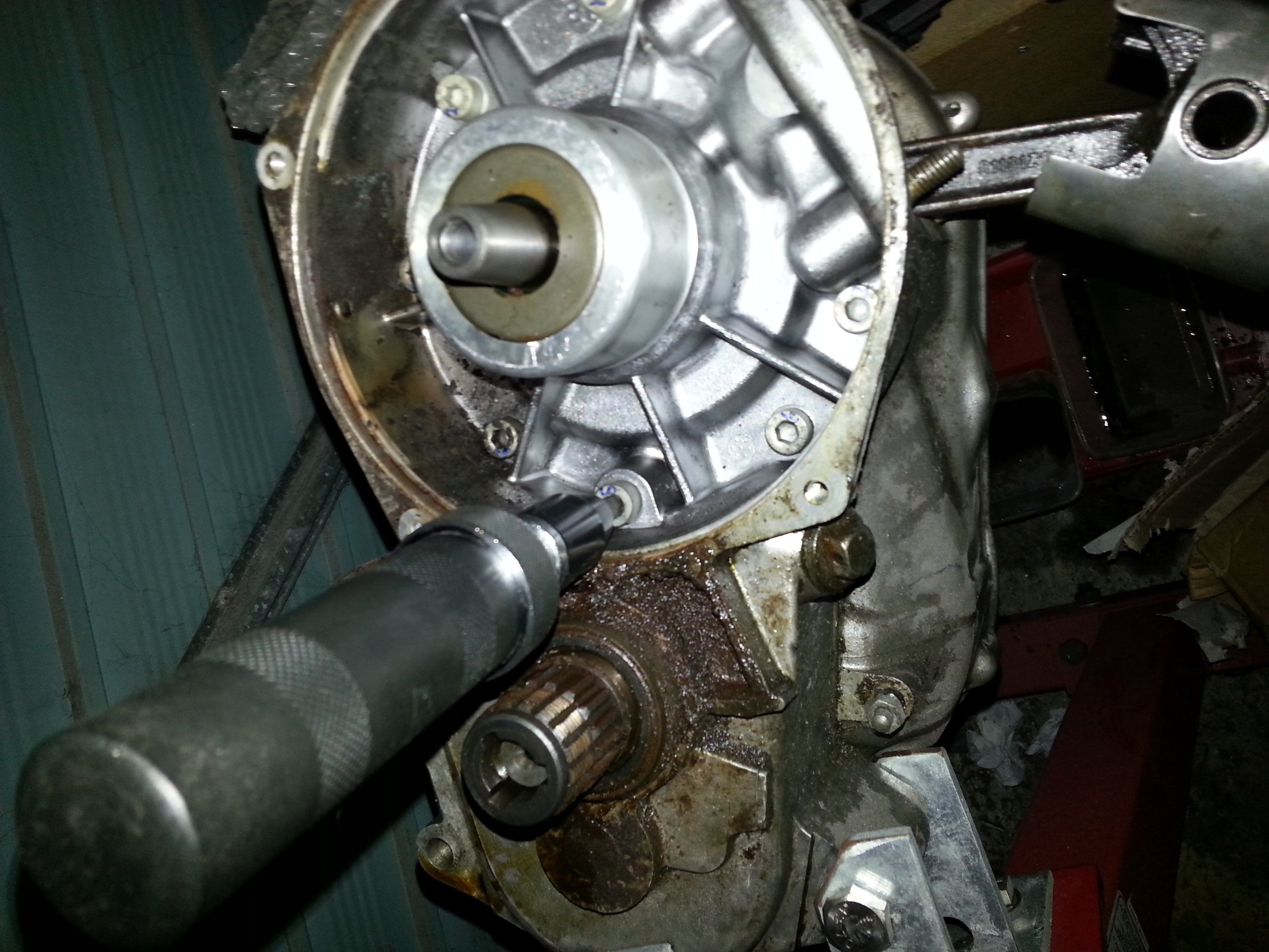
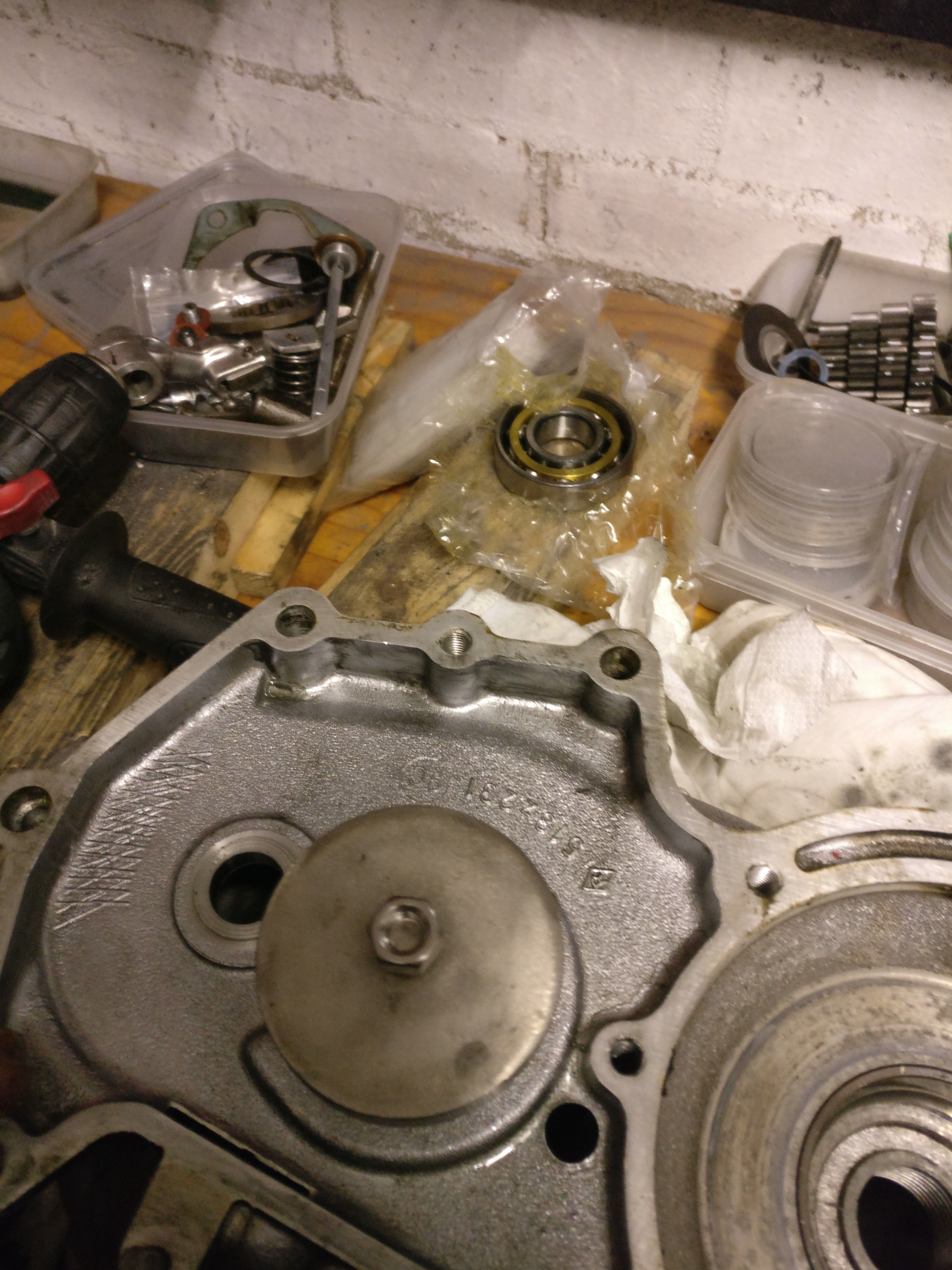
We proceed by removing the flywheel and the clutch assembly. First we take off the pressure ring:
With the ring removed, do not forget to take out the three pressure pins (it’s the pins like the one sticking out below the gear shaft on the picture below):
I made a mistake in the next step, which is to remove the circlip before removing the flywheel. Removing the flywheel will put tension on the chain which in turn will make it very hard to remove the circlip. So first we take the tension off the clutch assembly. For this we will make some tools to replace the standard Zundapp workshop tools. A threaded bush and some bolts will do the job:
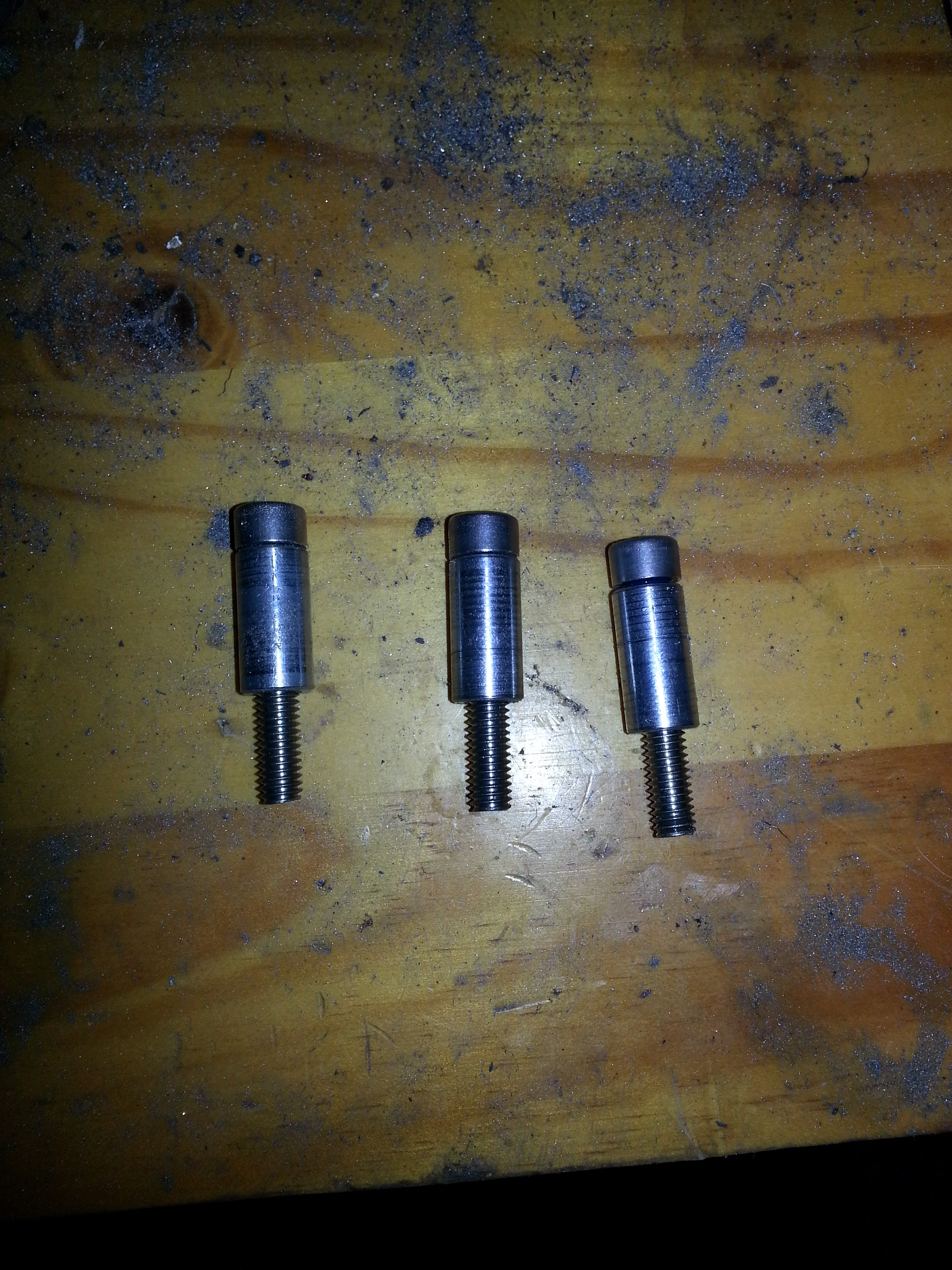
I think mine were 45mm long allen head bolts with 20 mm threaded bushes M6 with a 10mm outer diameter screwed on. I used loctite to keep the bushes in place. Insert them as follows to relieve clutch pressure:
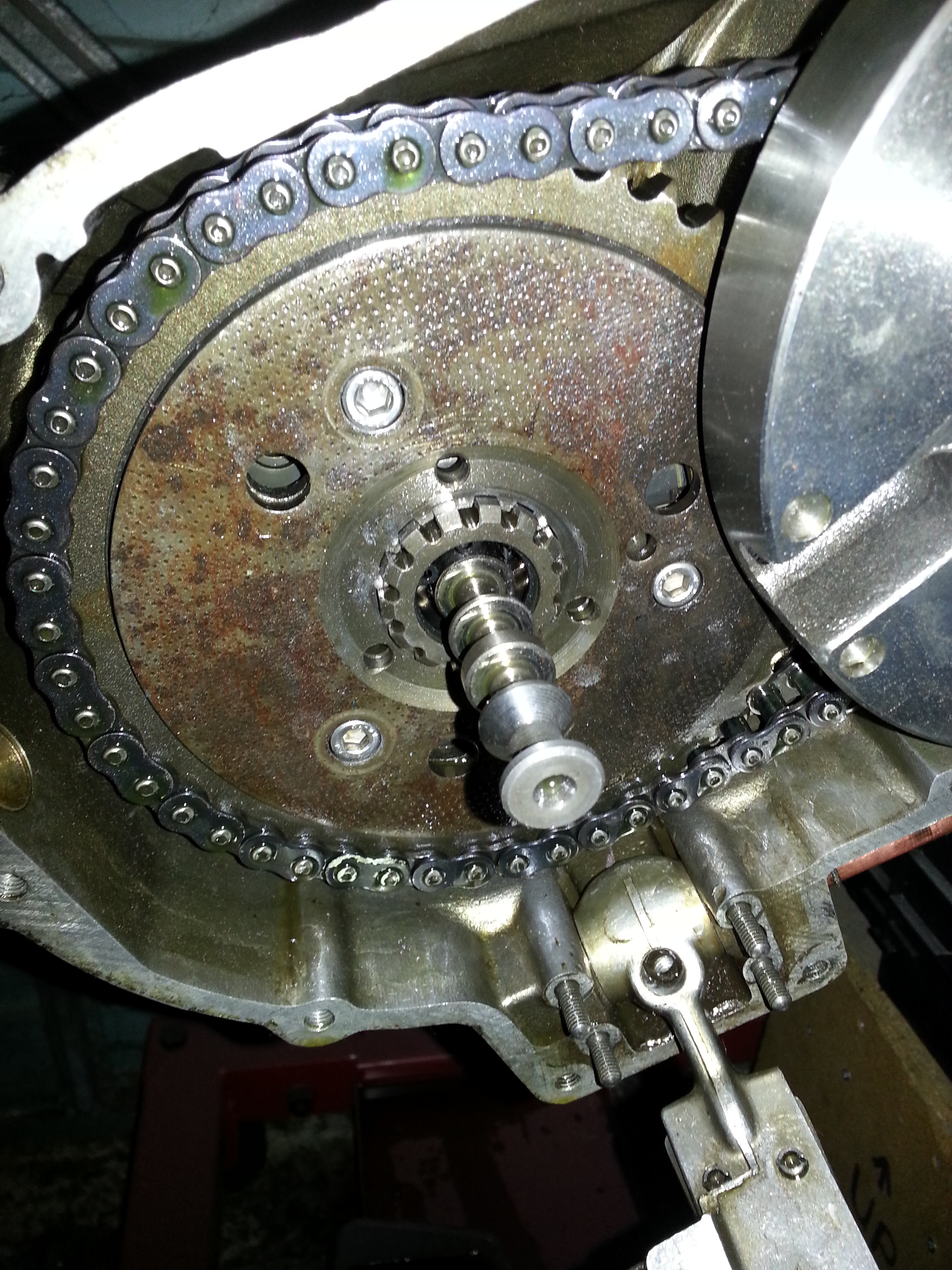
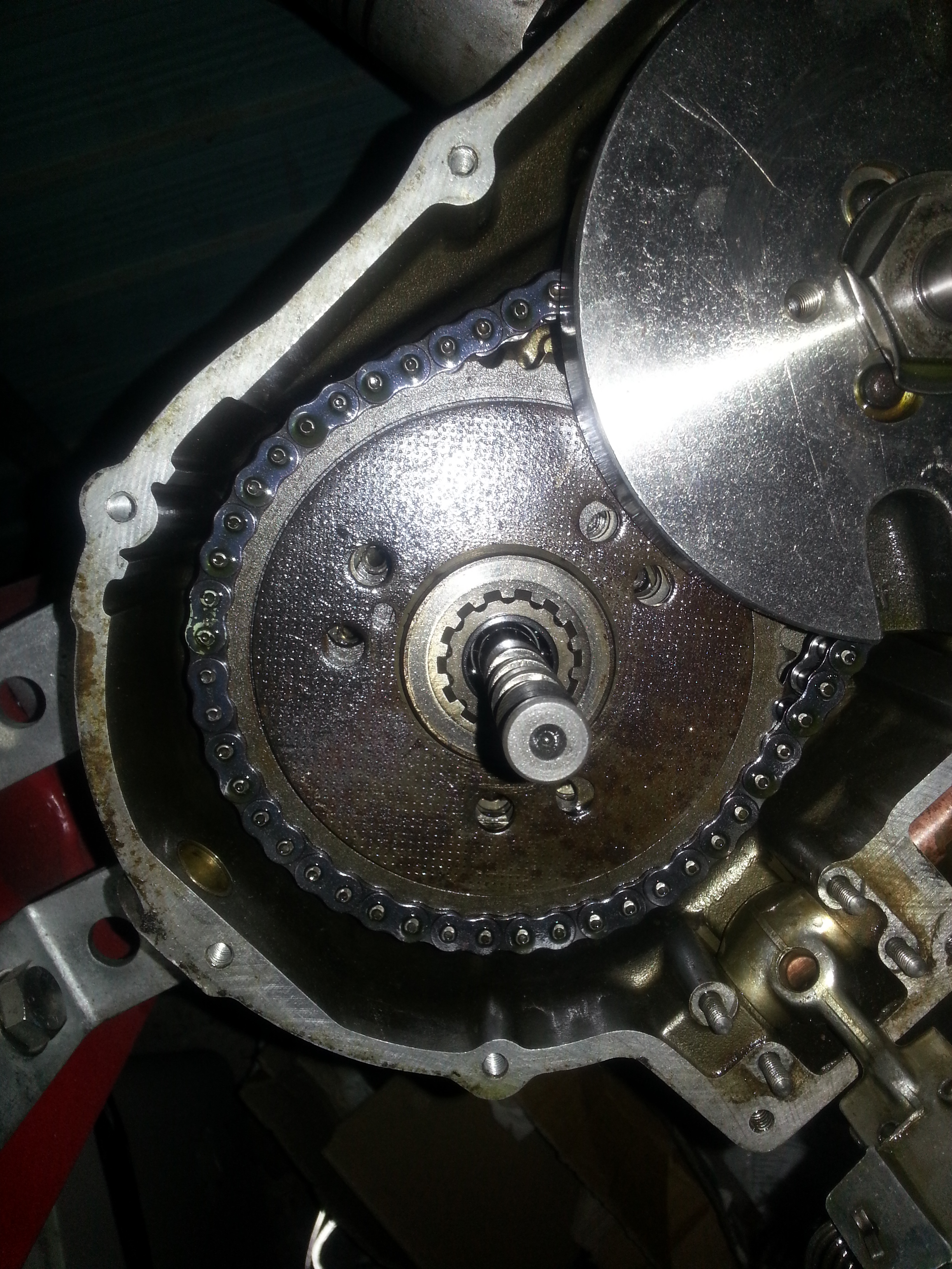
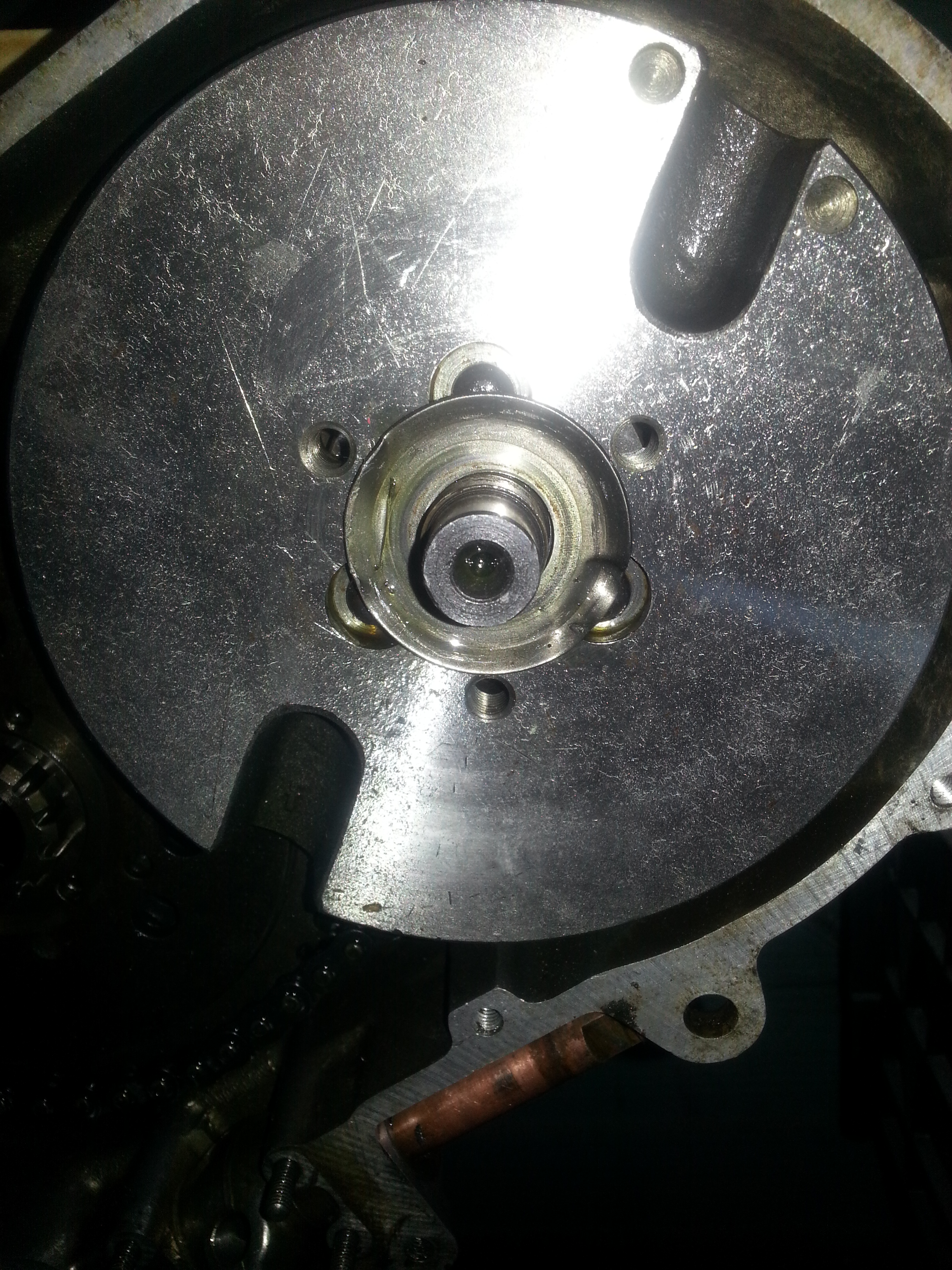
With the pressure reduced, remove the circlip (already done in this picture); do not forget to do so! With the circlip removed we can remove the flywheel. First, we’ll flatten the retaining washer:
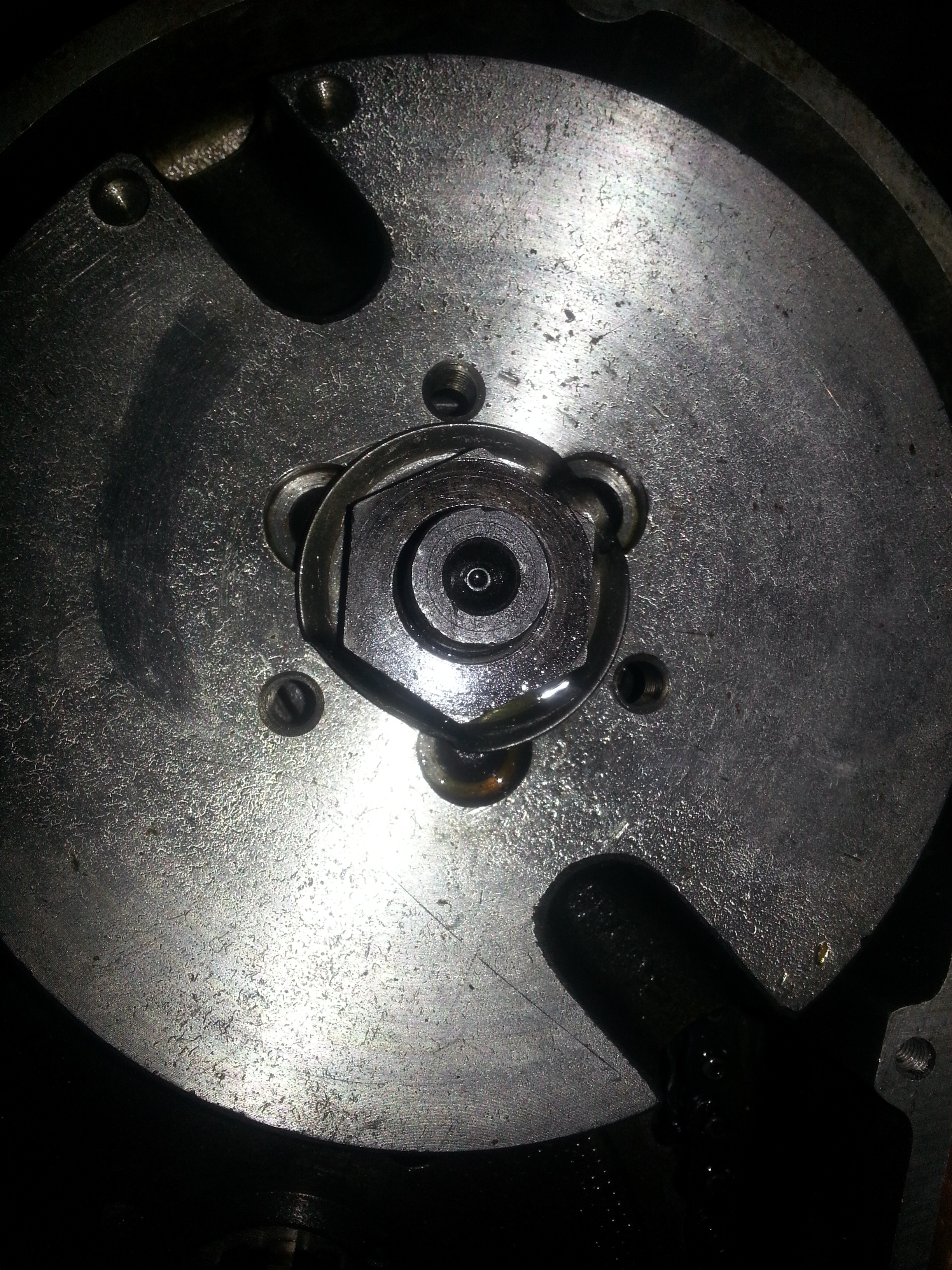
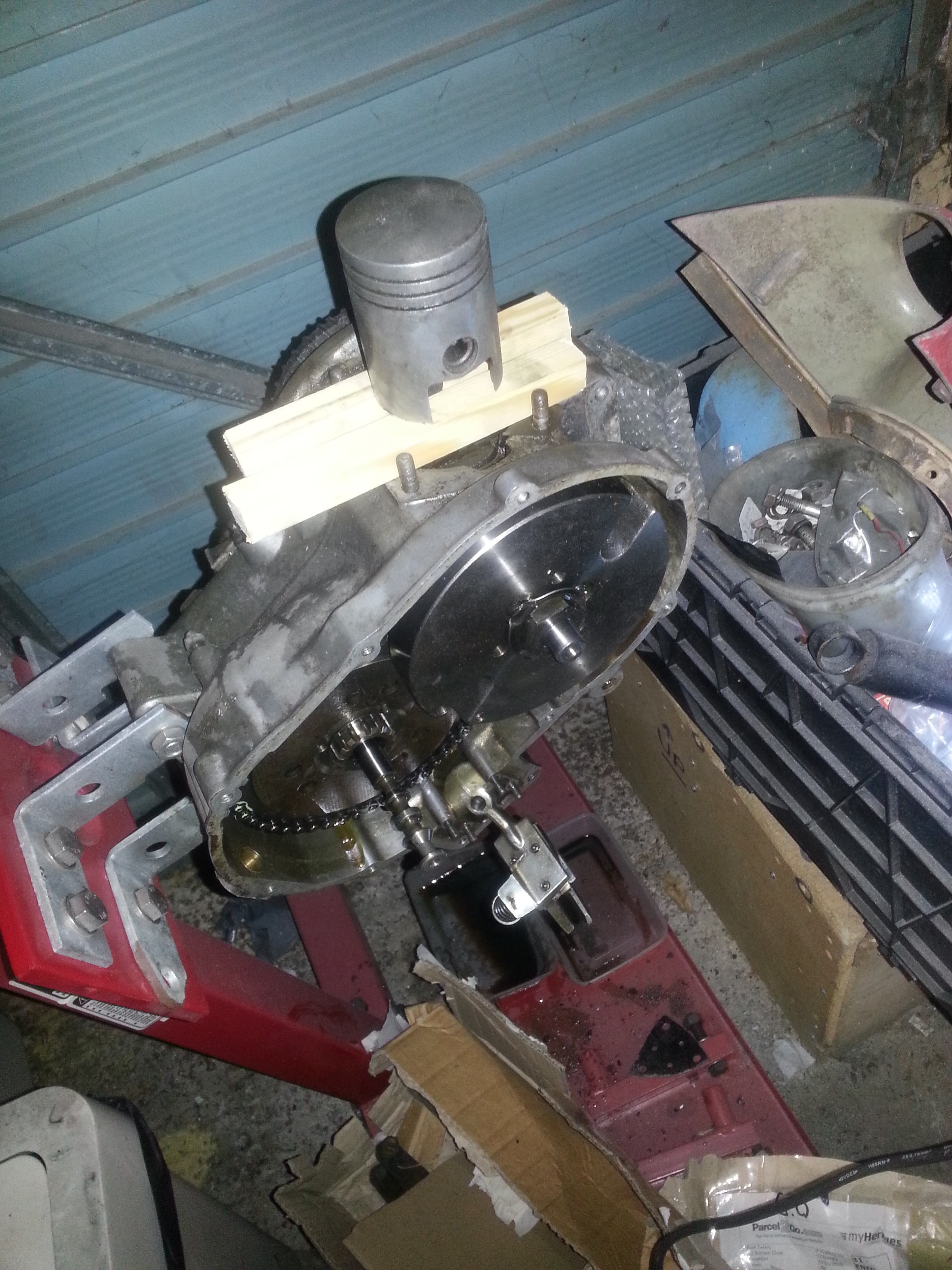
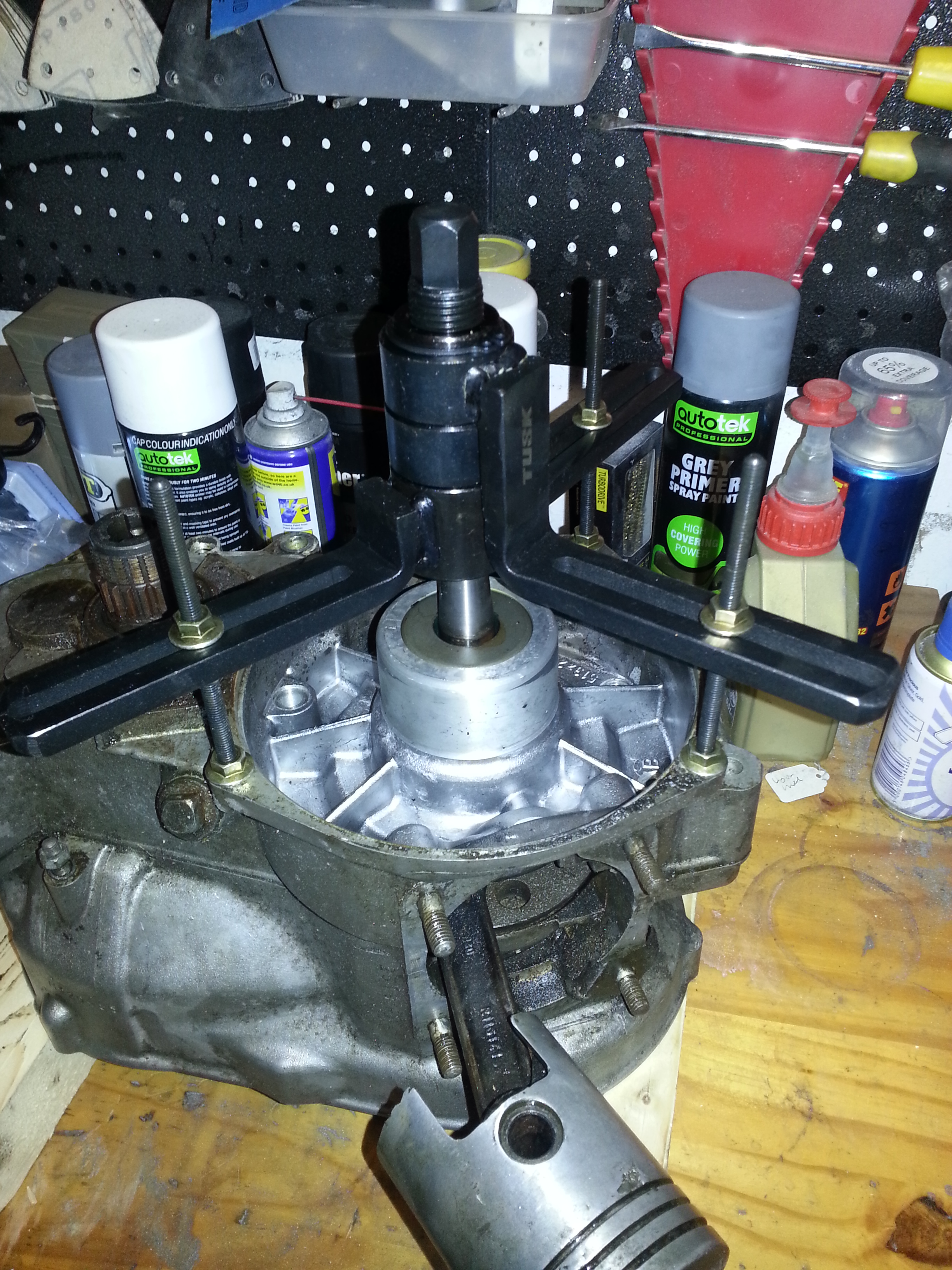
Then we will remove the nut. Please note, this is left thread! I used a socket and an extendable socket wrench to loosen the nut after blocking the engine using the piston. I would have preferred a different solution as the amount of force needed was substantial and I’m not sure the connecting rod bearing like that much pressure:
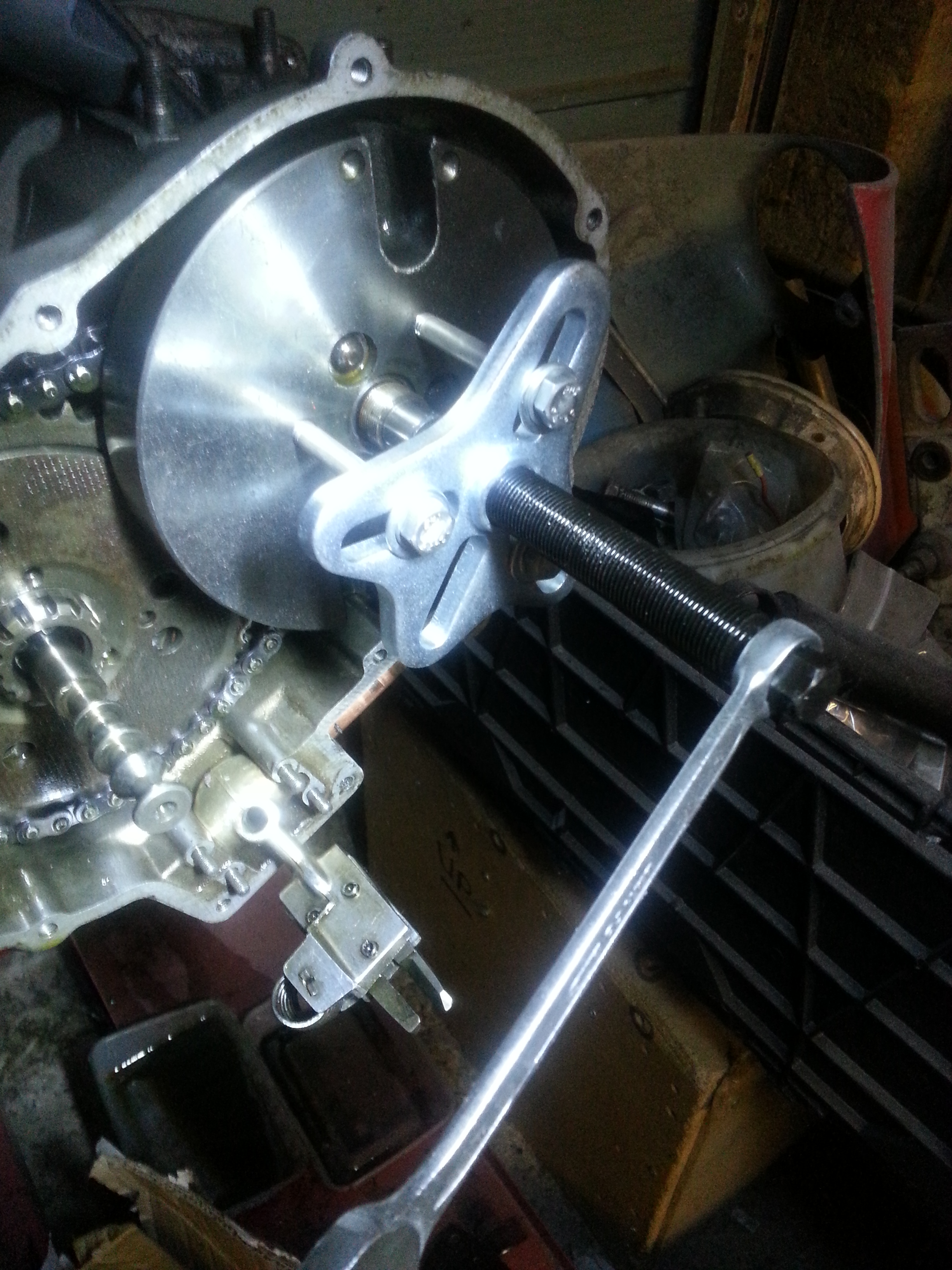
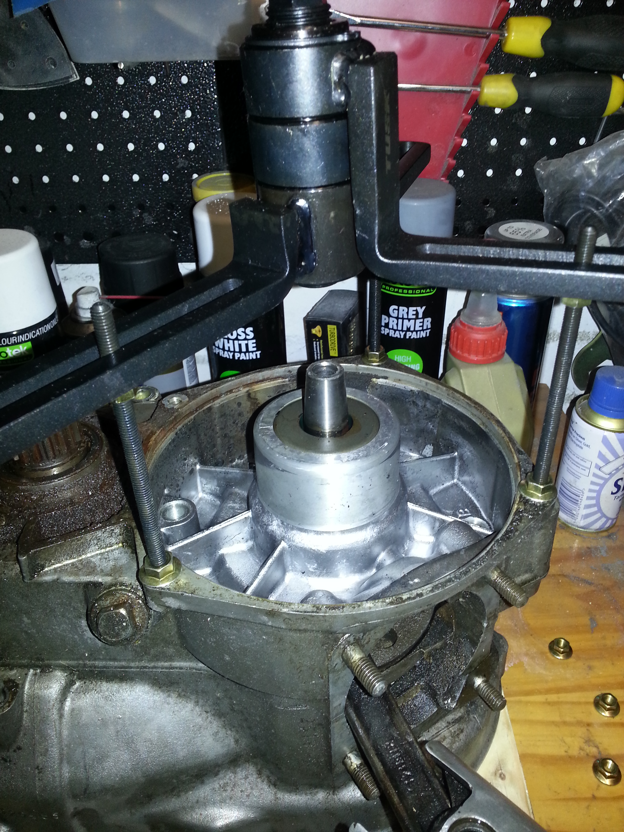
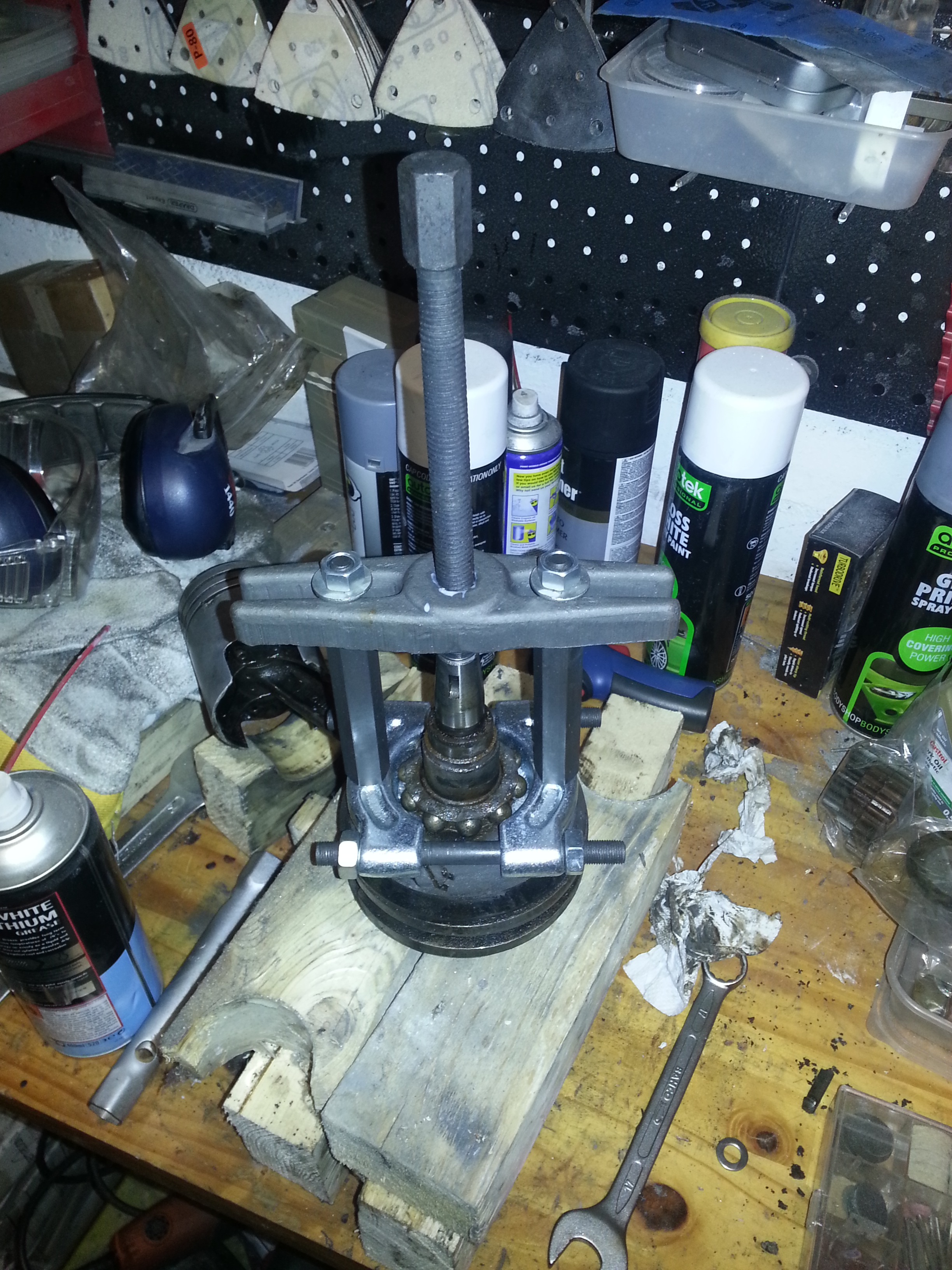
We can now remove the retaining washer and use a harmonic puller to remove the flywheel. Again, a lot of force needed:
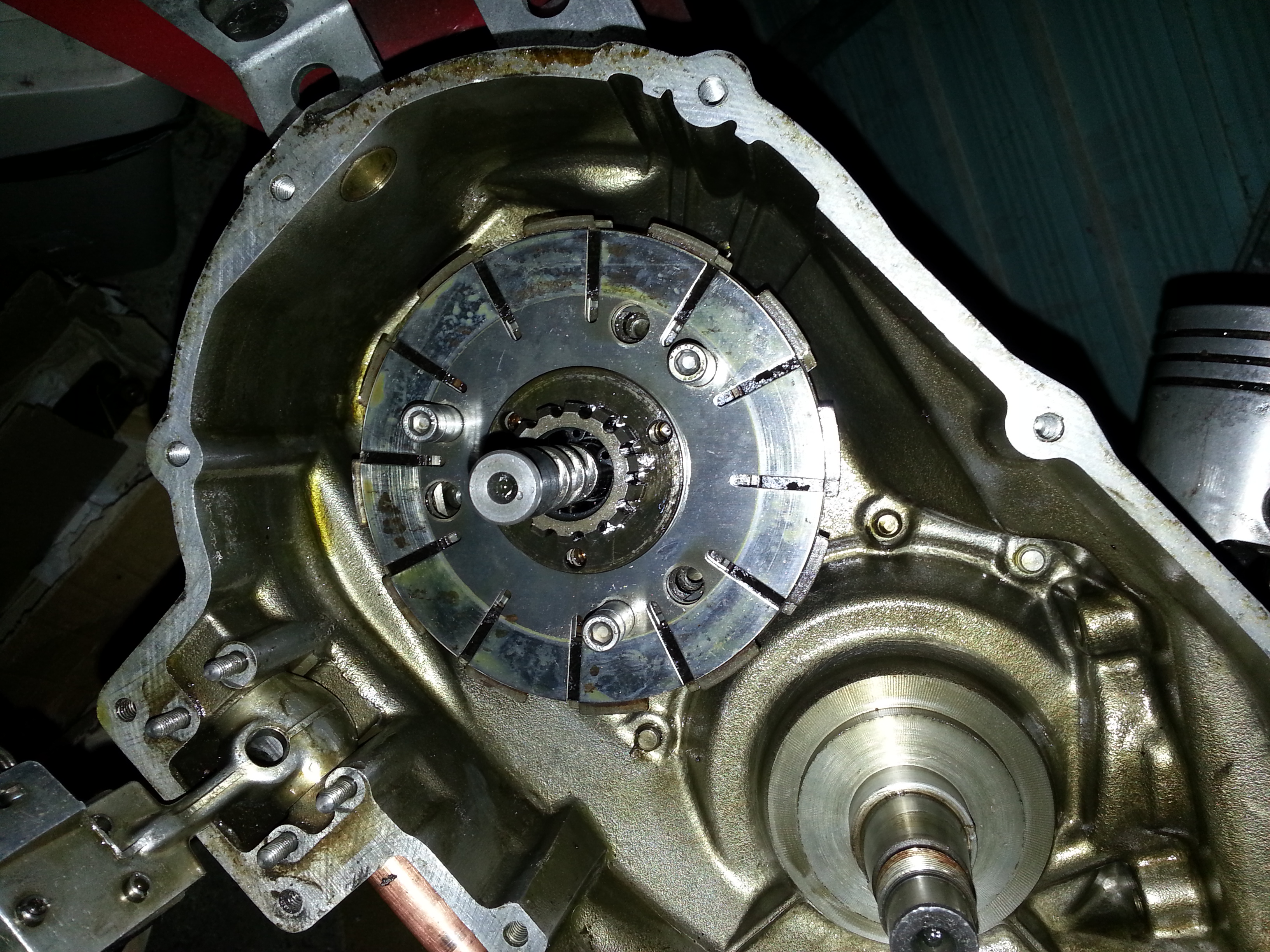
With the flywheel loosened, you can remove the entire flywheel and clutch sprocket in one go, including the chain right over the bolts we made earlier. The bolts will keep the clutch compressed lightly so you can take the plates off in one go. Be careful not to lose the wood-ruff key holding the flywheel in place.
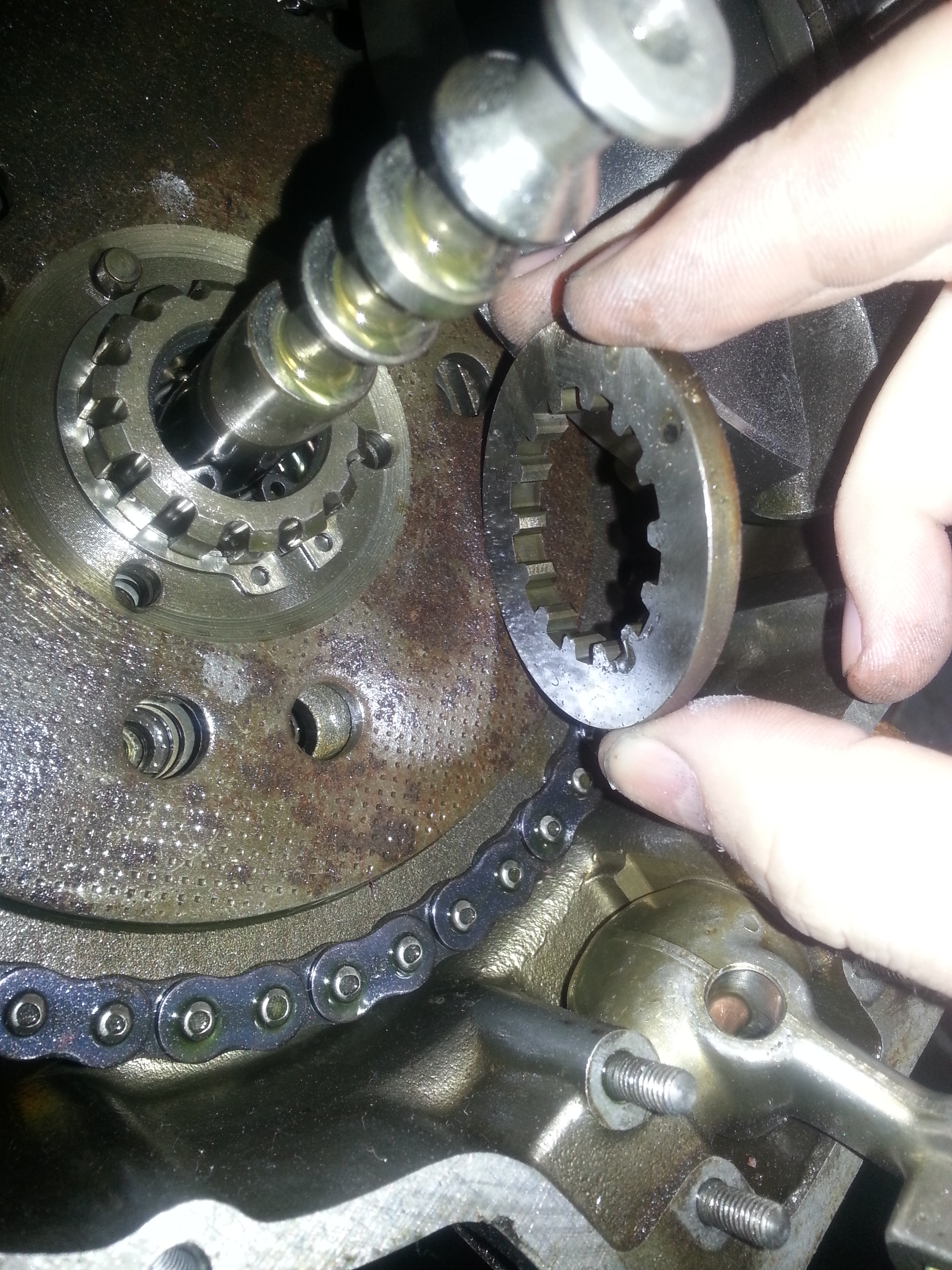
We can next remove the intermediate ring and sprocket under the clutch sprocket:
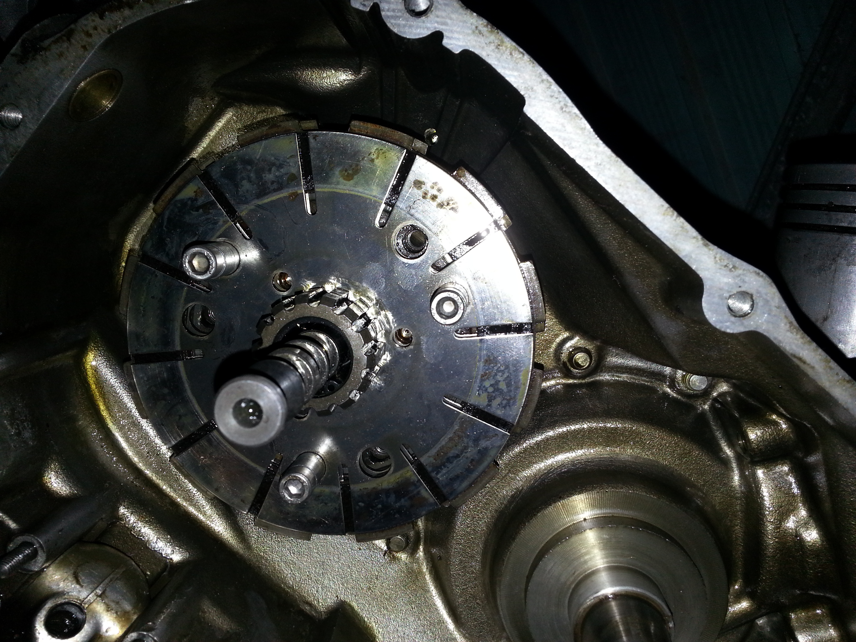
Underneath the right is another circlip to remove that holds the clutch plates in place:
With the circlip removed, the clutch plates can be lifted off in one go:
You will notice a final circlip on the gear shaft; do not forget to remove it before splitting the engine halves apart!
Next we’ll spend some time removing the final engine bolts:
With all the volts removed and all circlips; it is time to split the engine halves. A crank case puller is not a luxury here; it will allow the engine to be split without damage:
Gently does it:
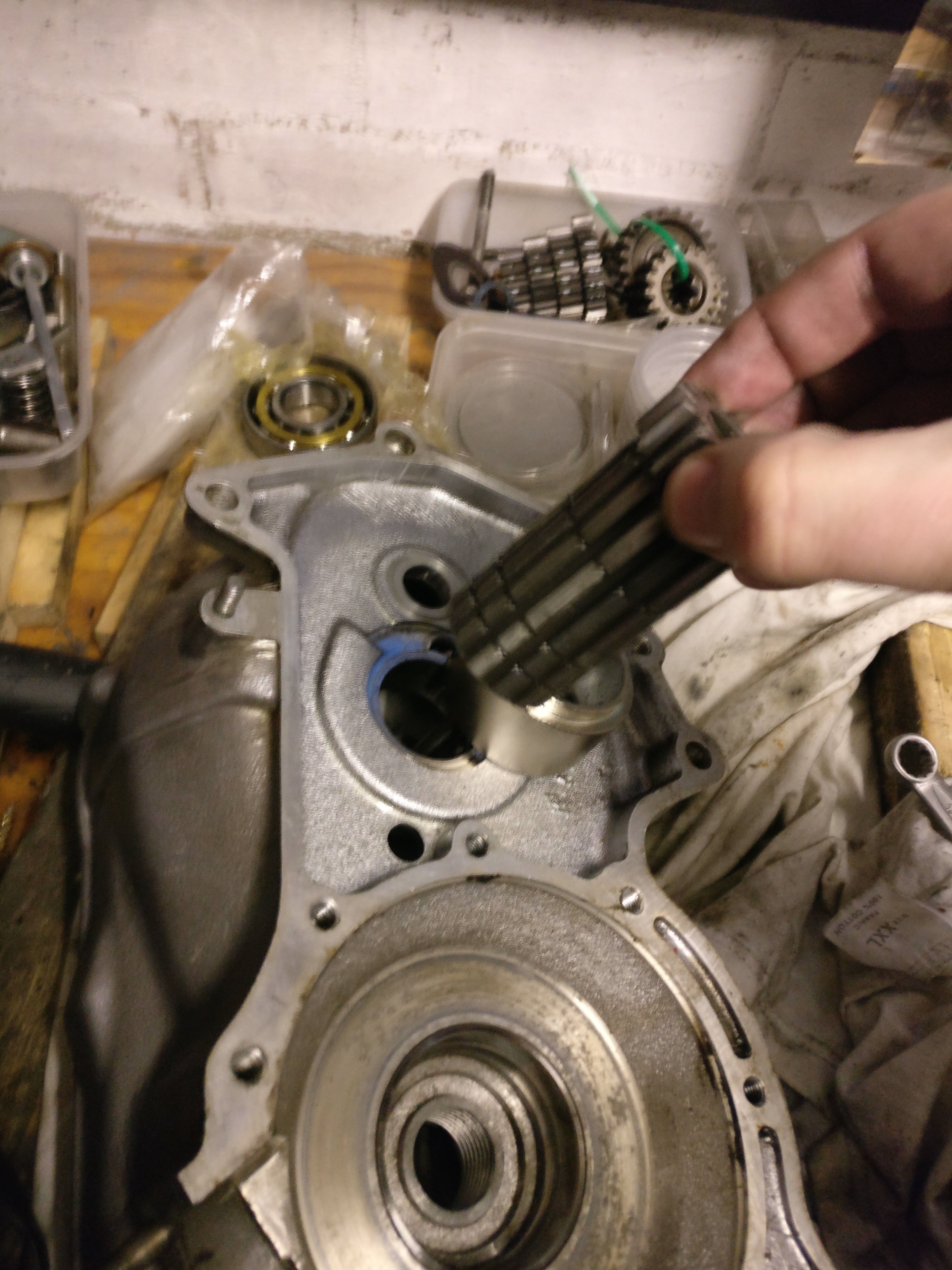
As always, be careful that parts don’t fall out. In my case a shim washer fell out and luckily I could see where it came from. To proceed we’ll take the gear shaft out. First pull it out till you see the gears on the shaft:
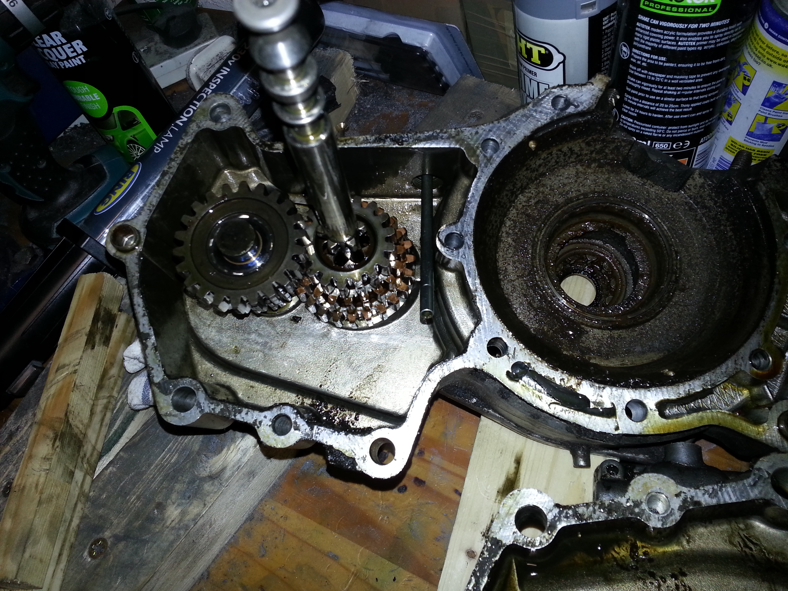
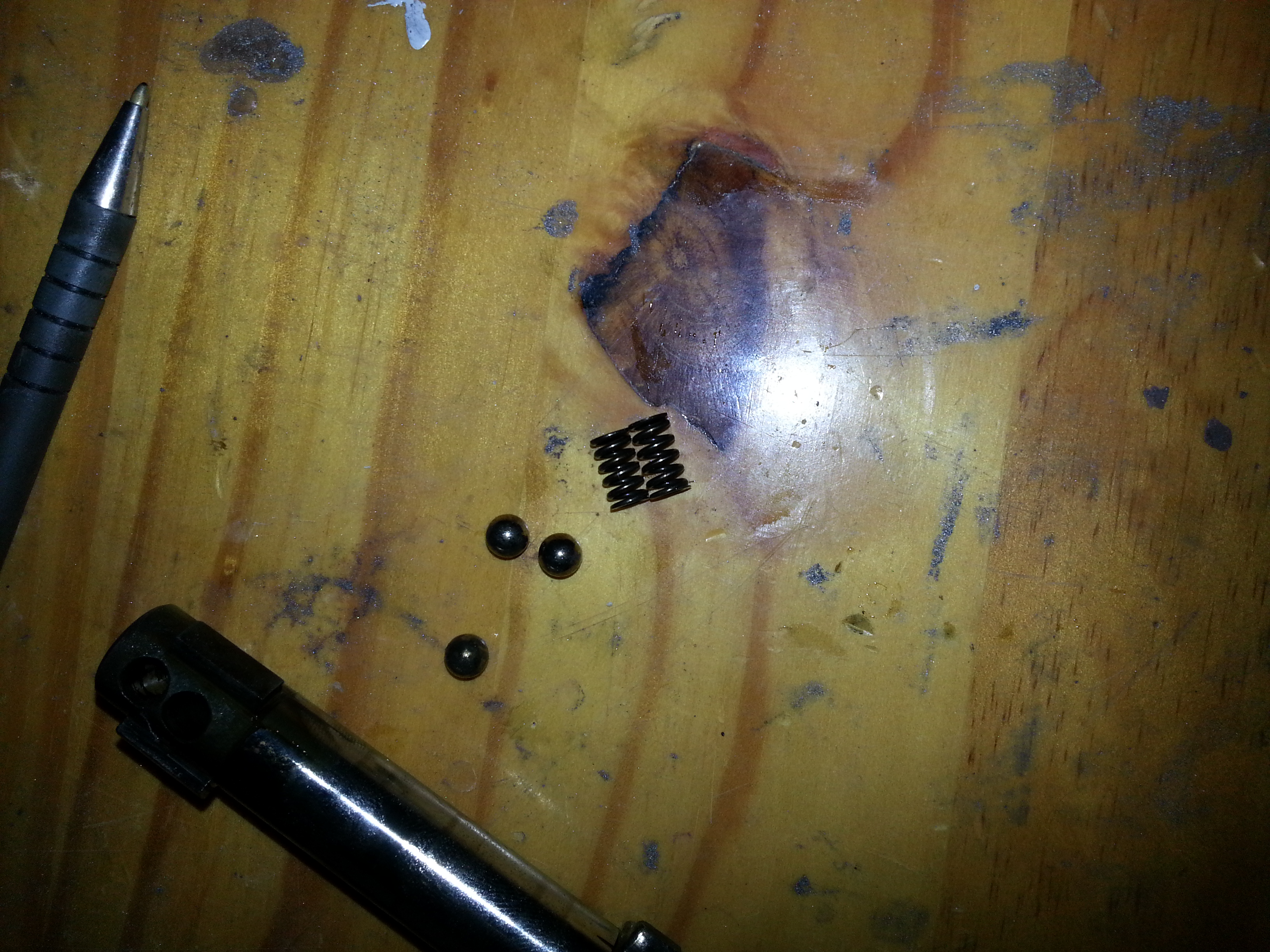
Next be very careful as the shaft holds spings and balls:
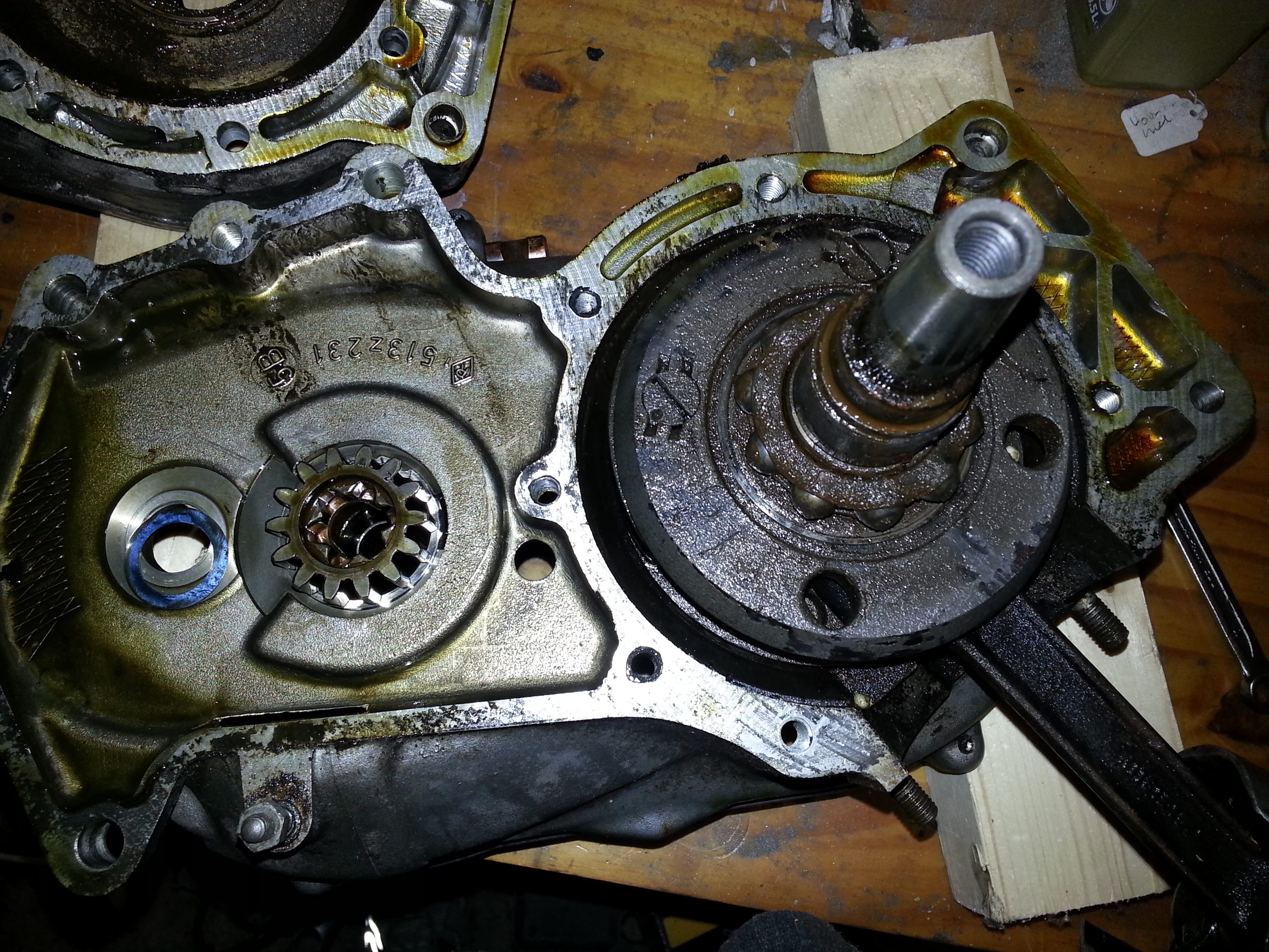
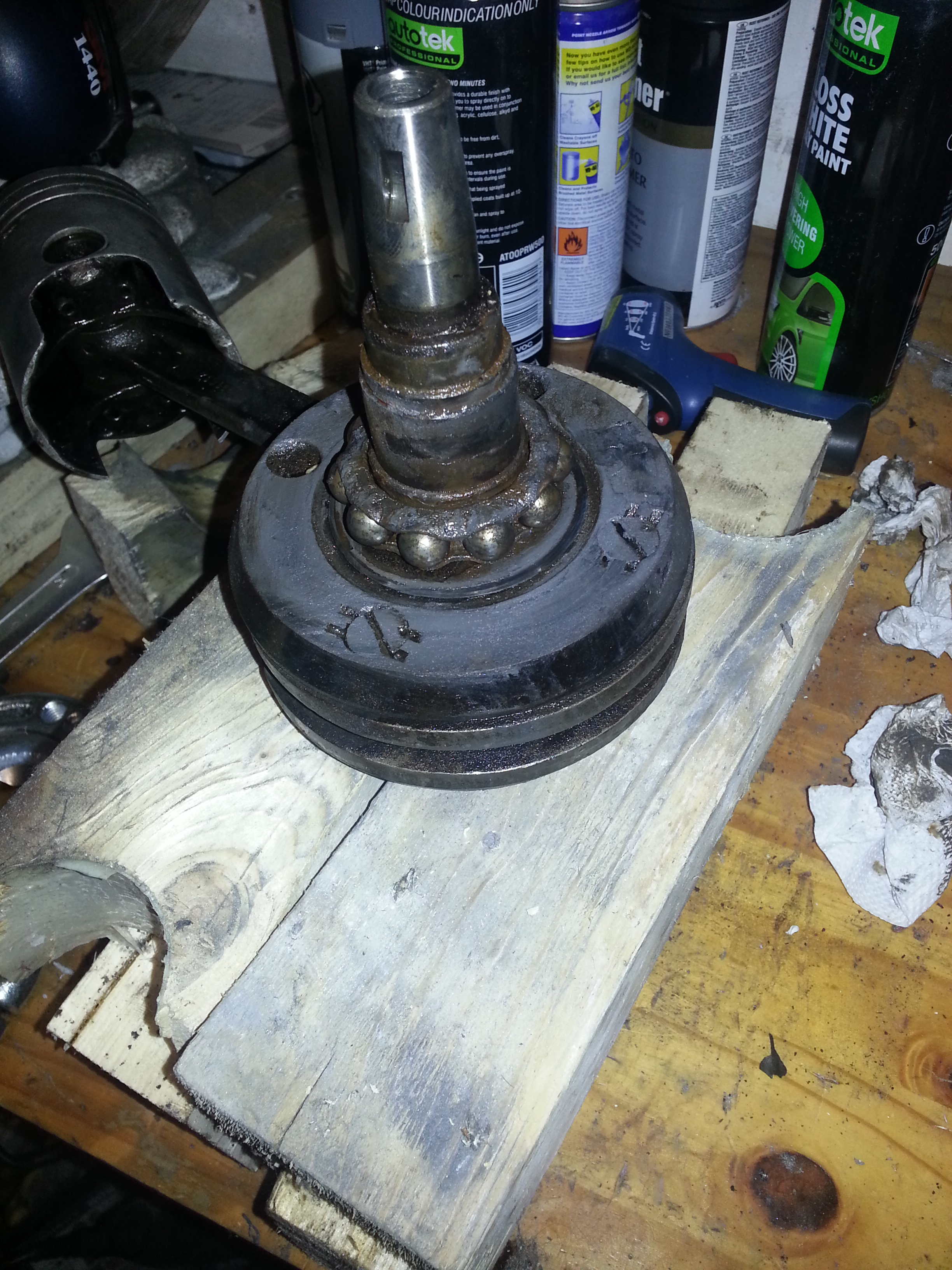
The clutch hub, sprockets and roller bearing cage can now be removed and gently tapped through the bearing; alternatively the housing around the bearing can be heated to facilitate:
Dont forget to mark the shim washer underneath the pinion block:
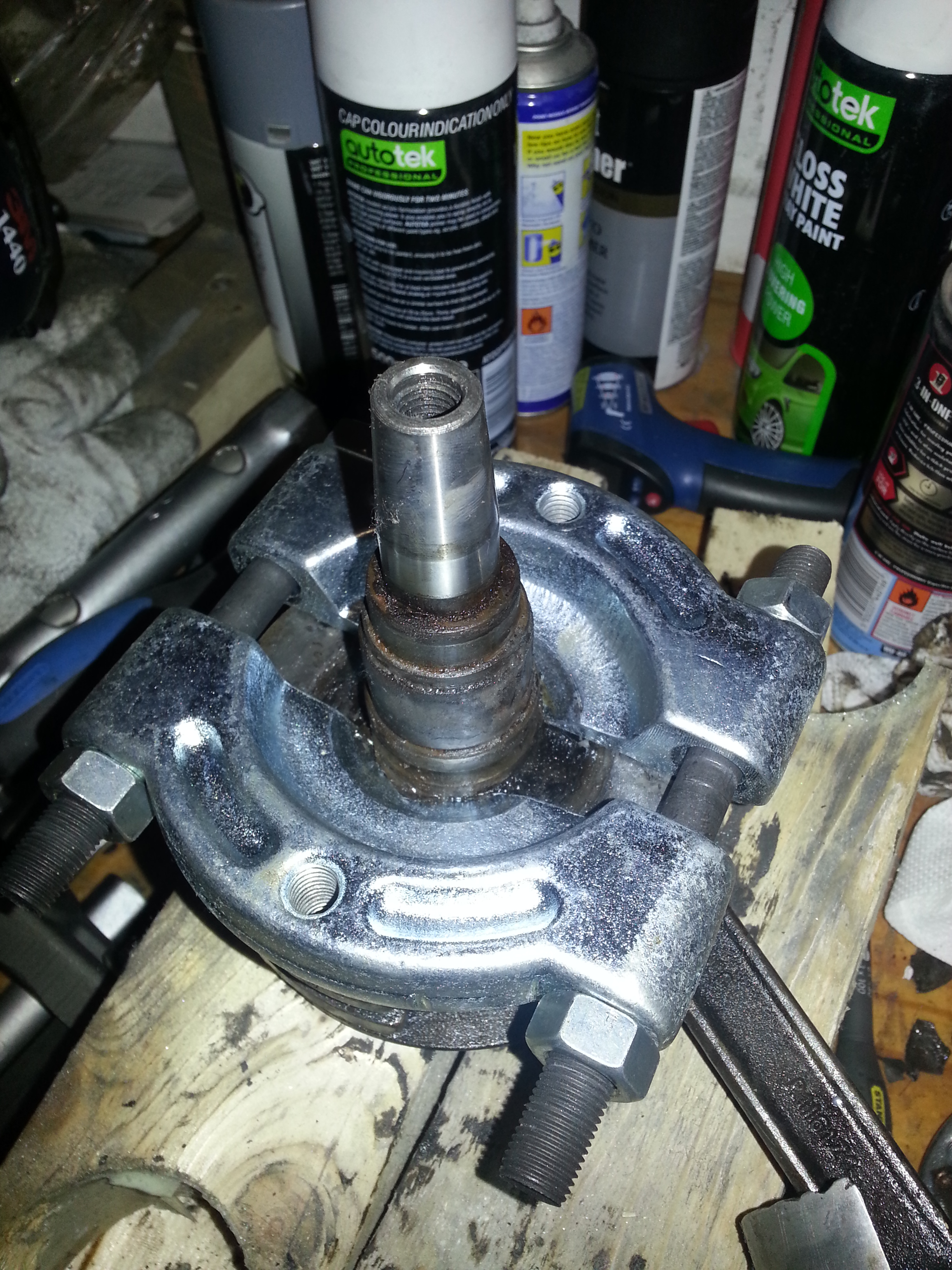
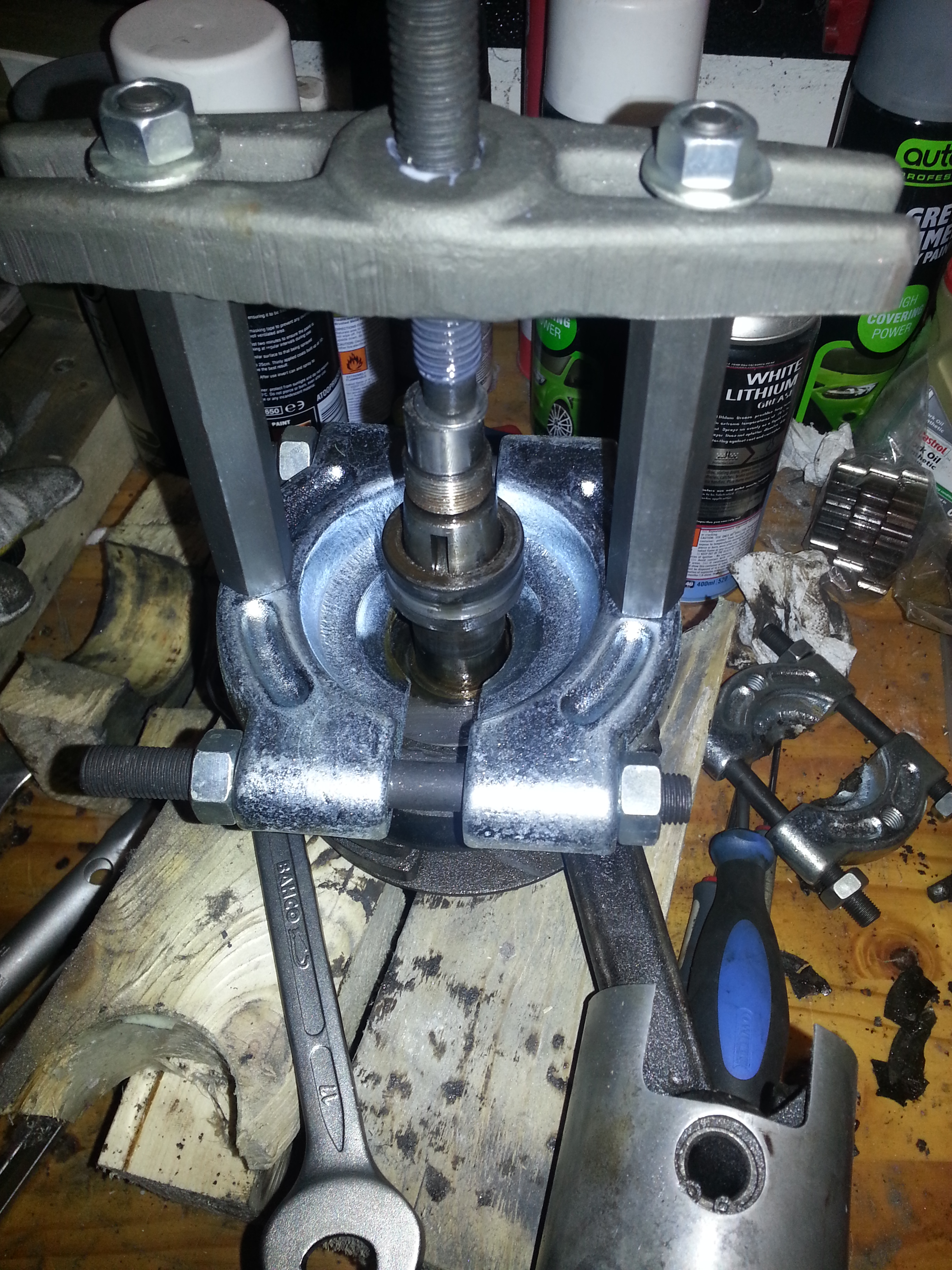
To remove the clutch gear, do the following on the clutch side; use a stud rod with threading both ends and put a bearing installer ring on on the clutch side:
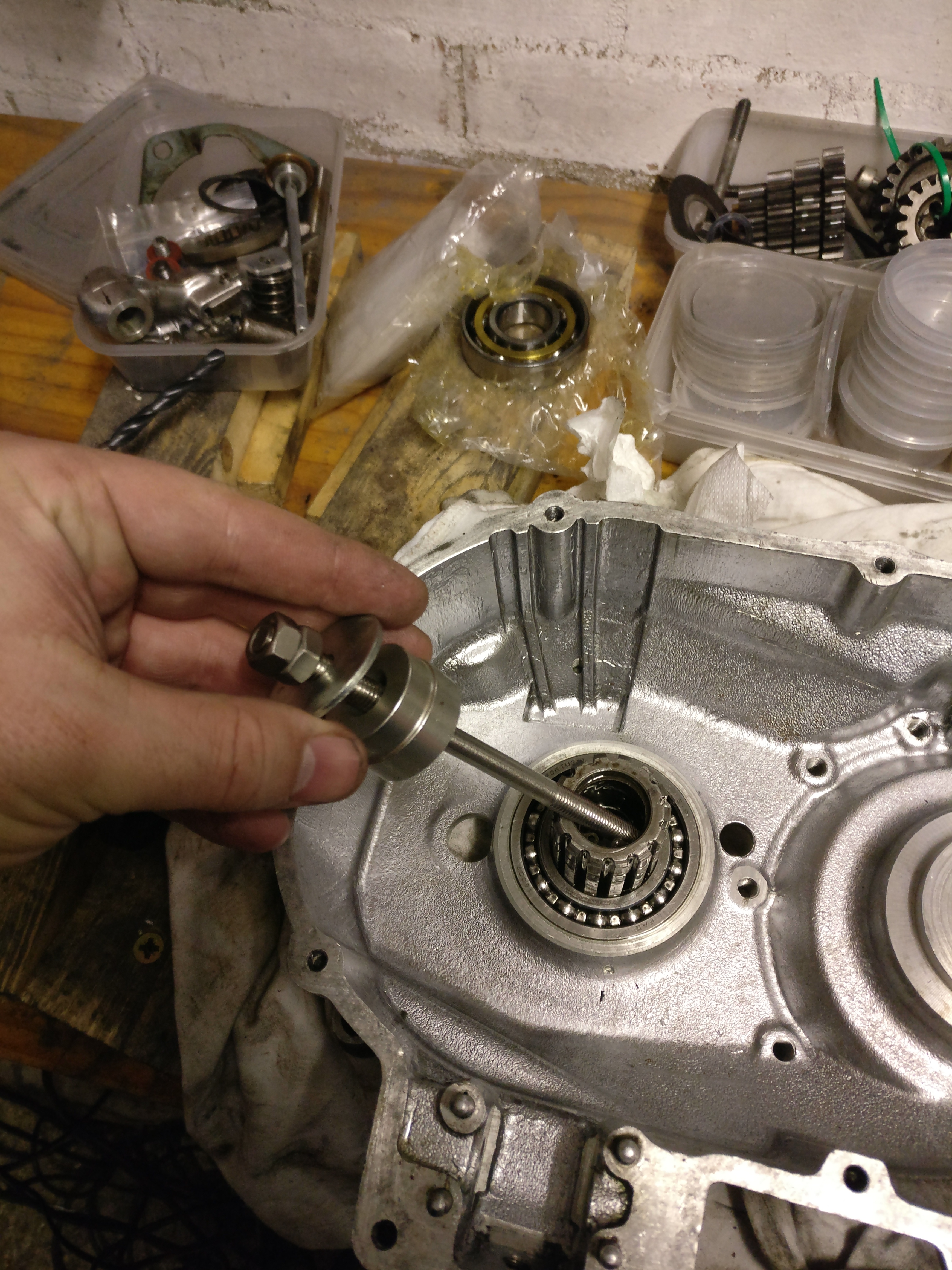
Then put an oil seal installer ring on the other and put a metal disc on top:
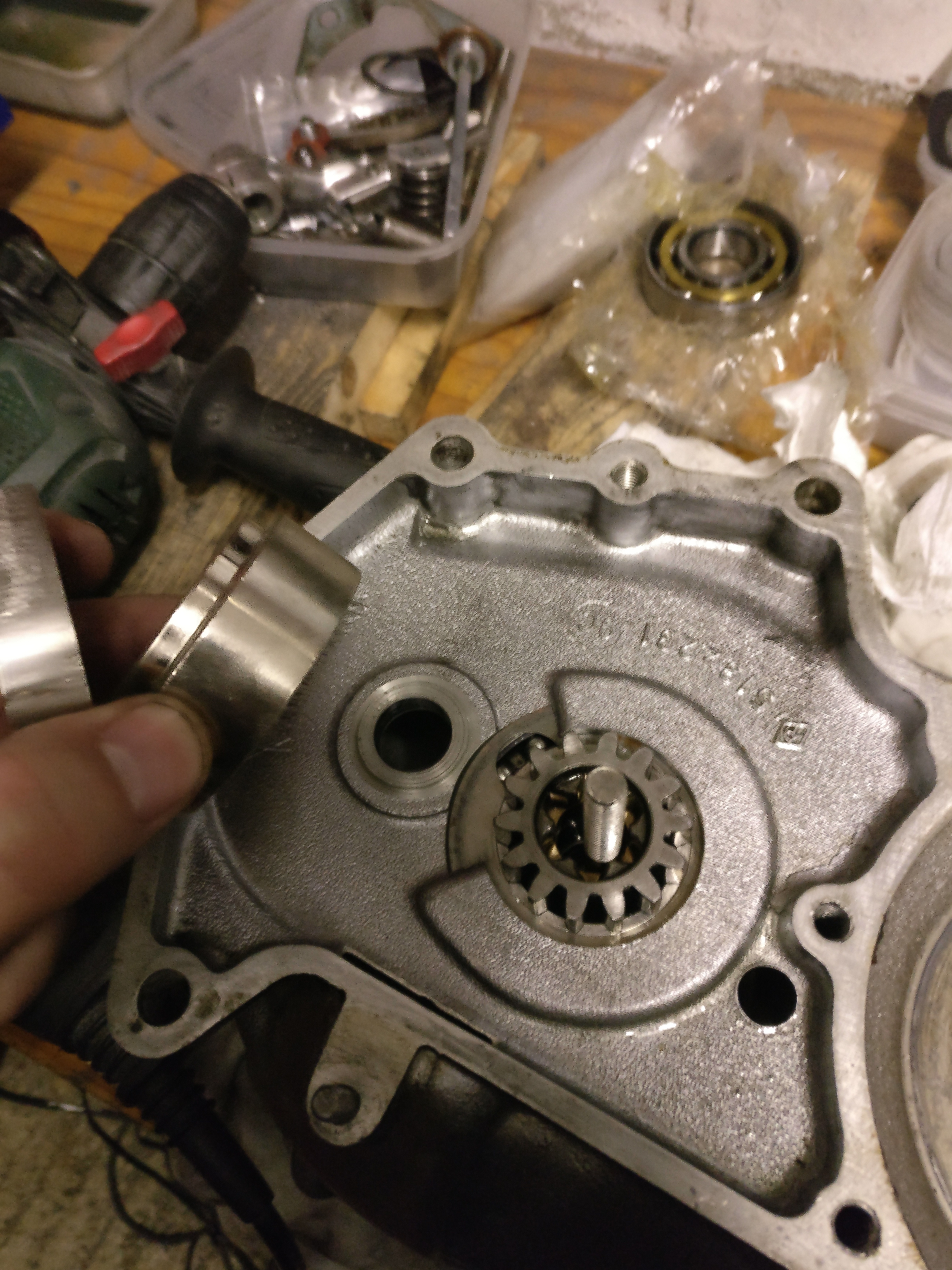
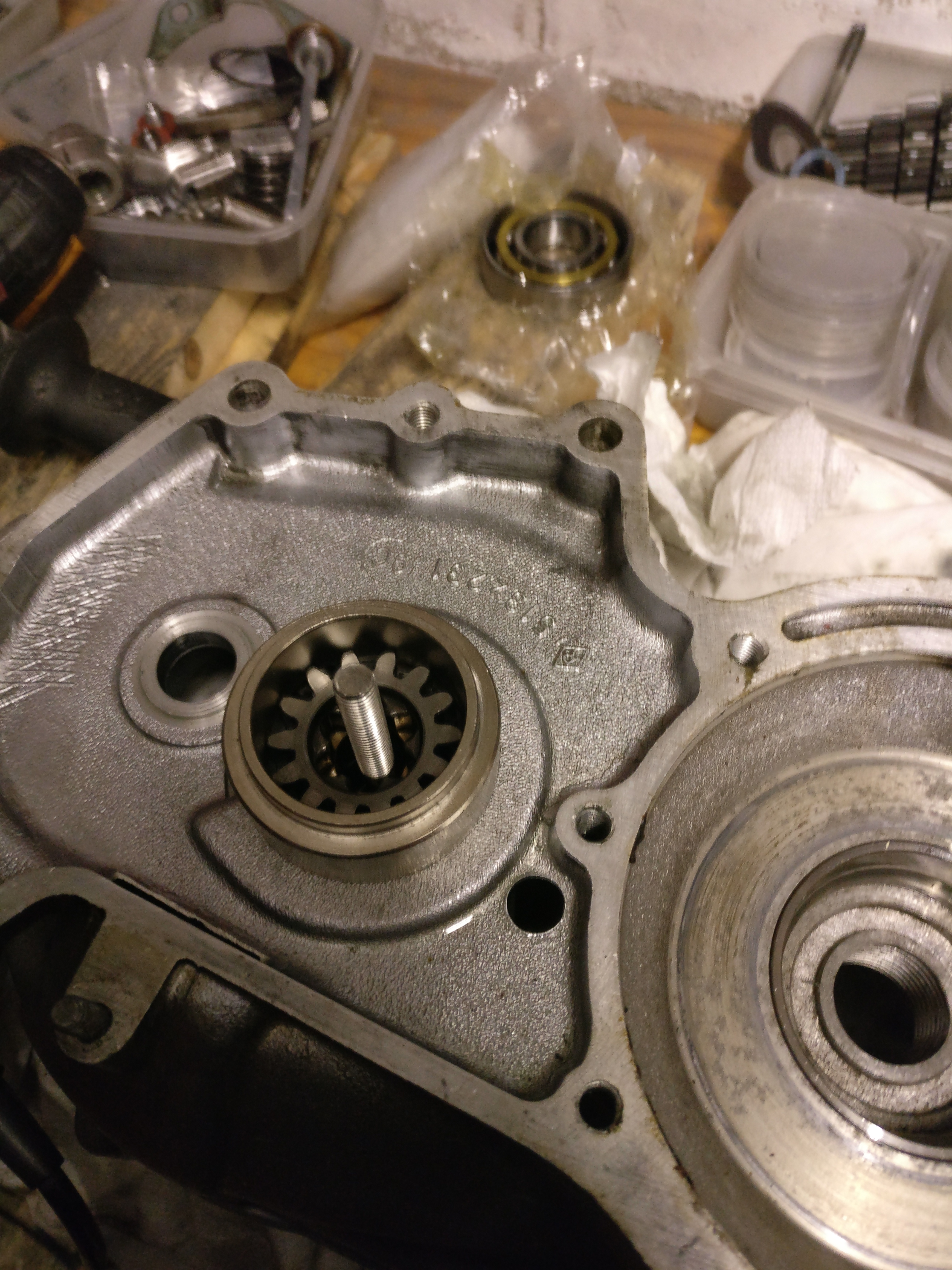
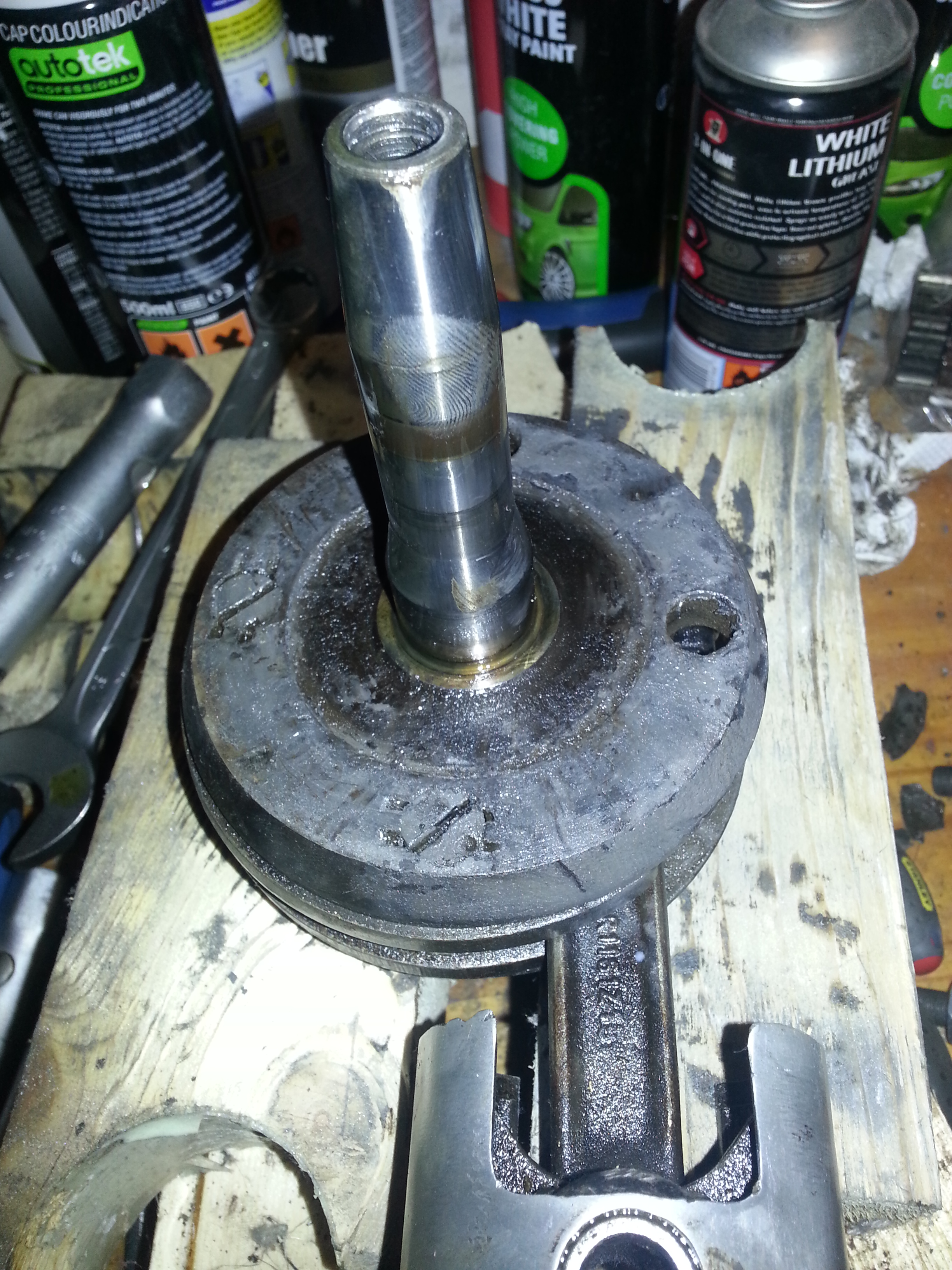
Then turn at both ends and the clutch gear unit will pull itself out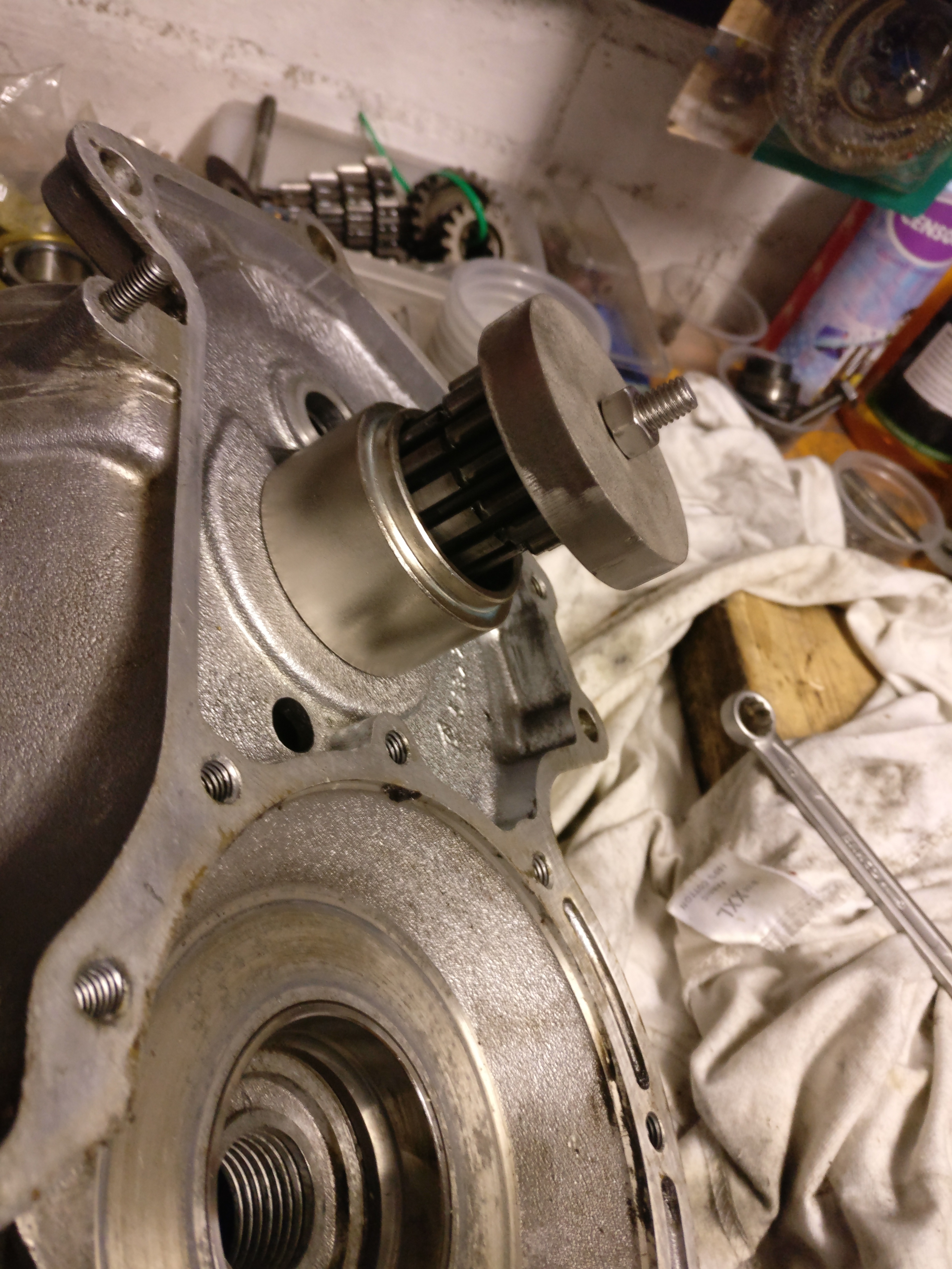
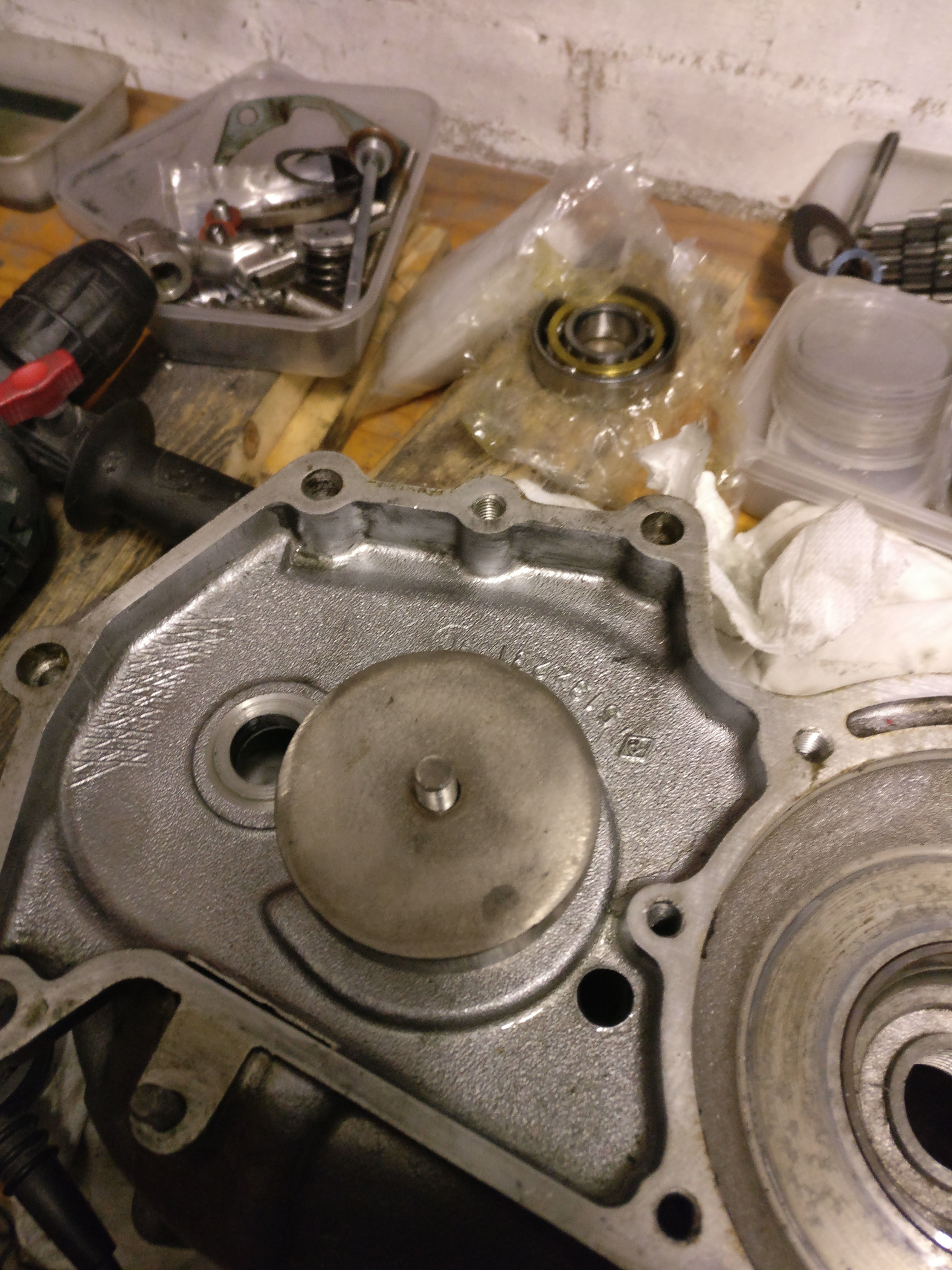
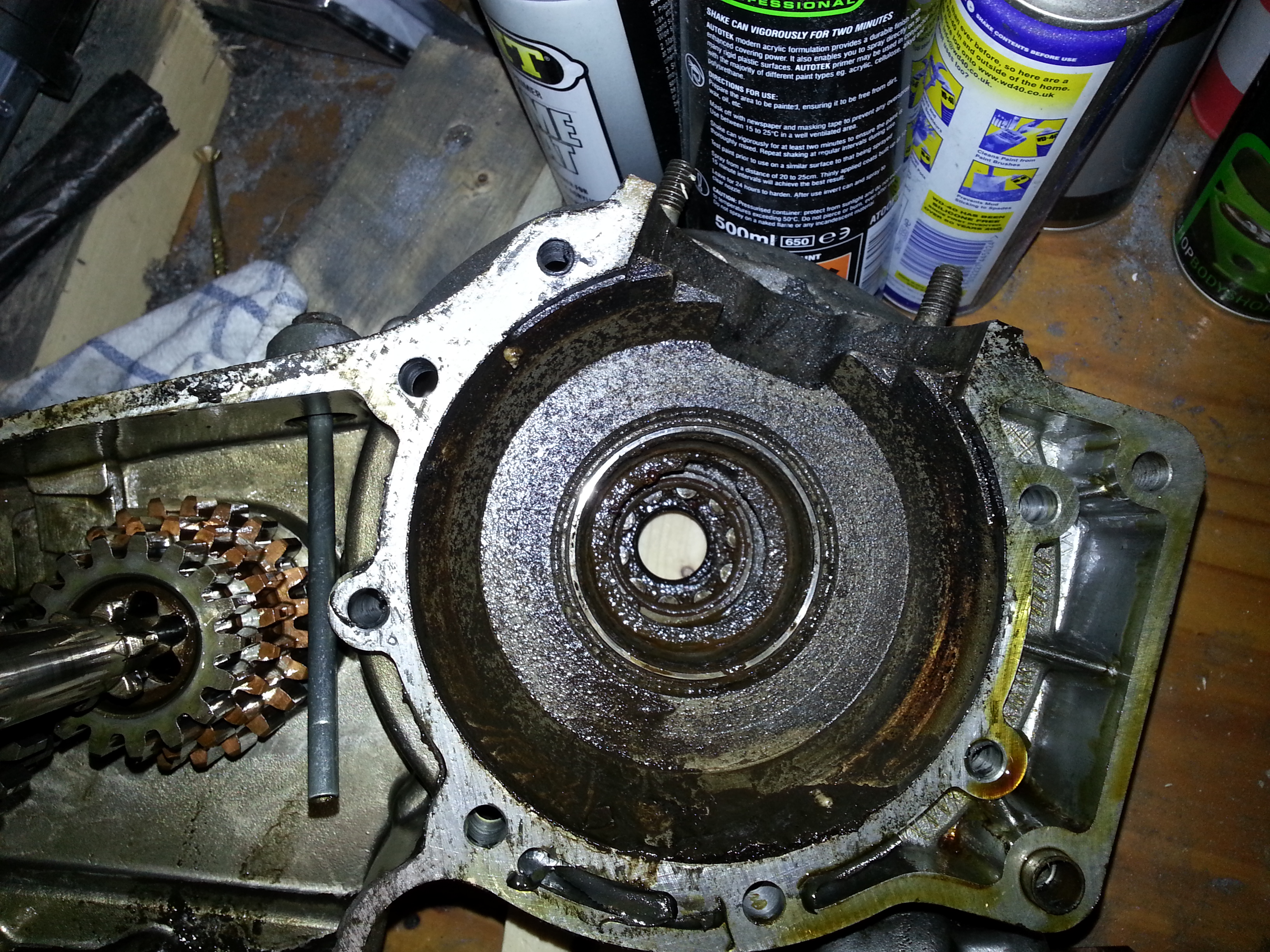
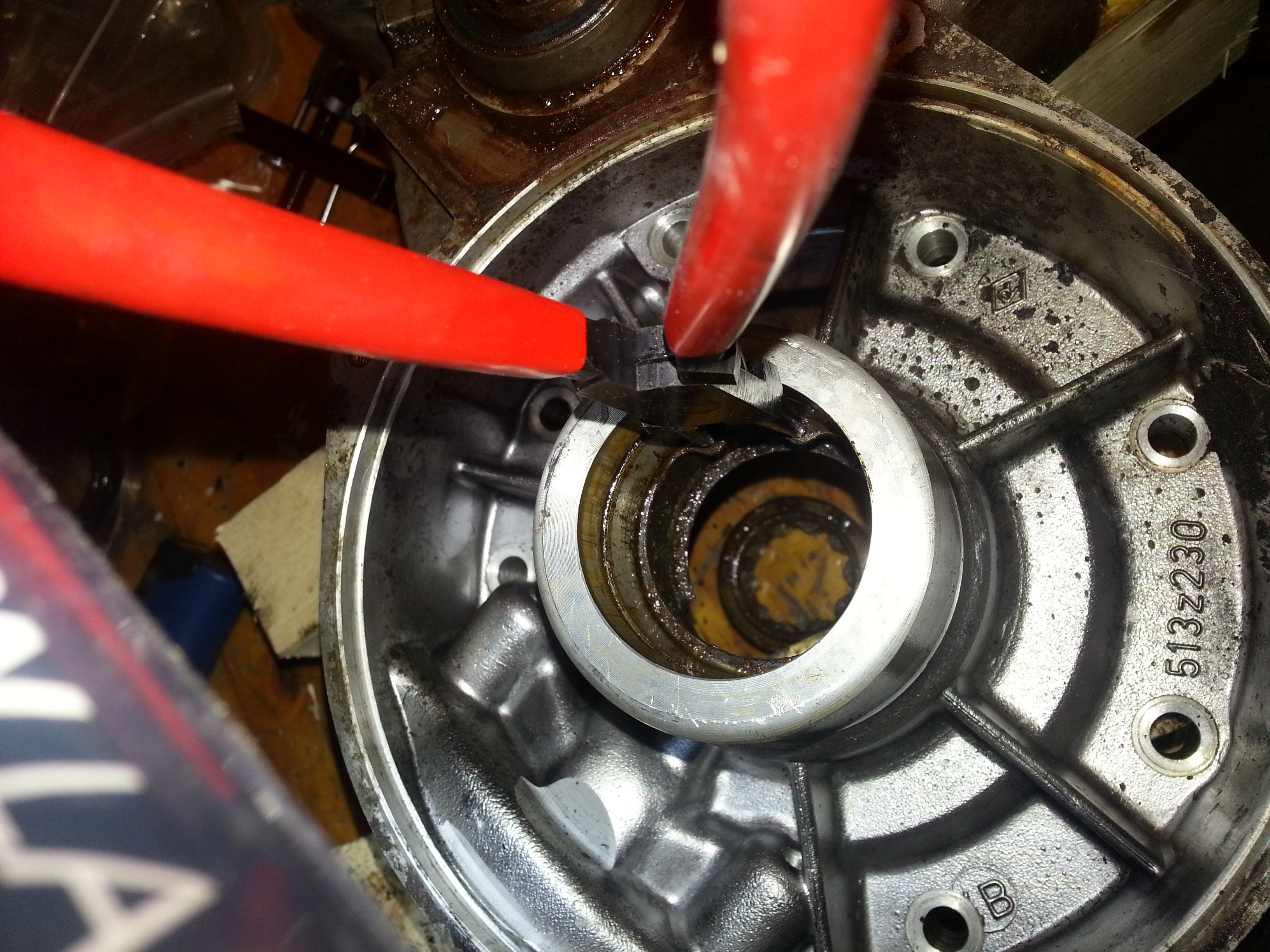
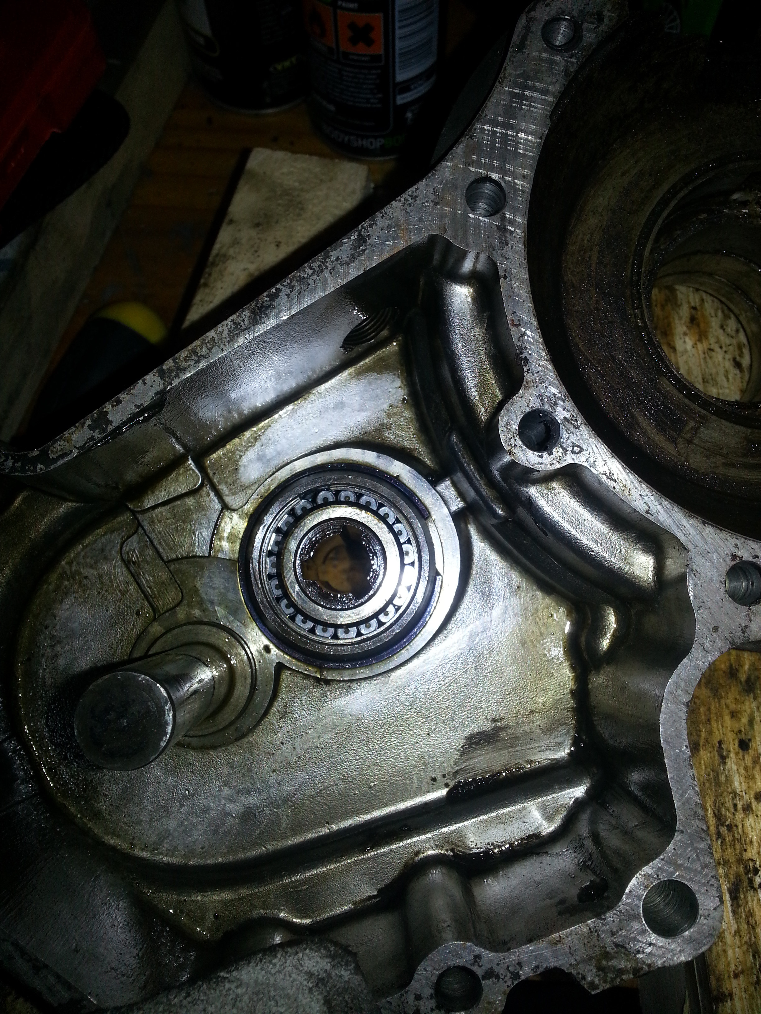
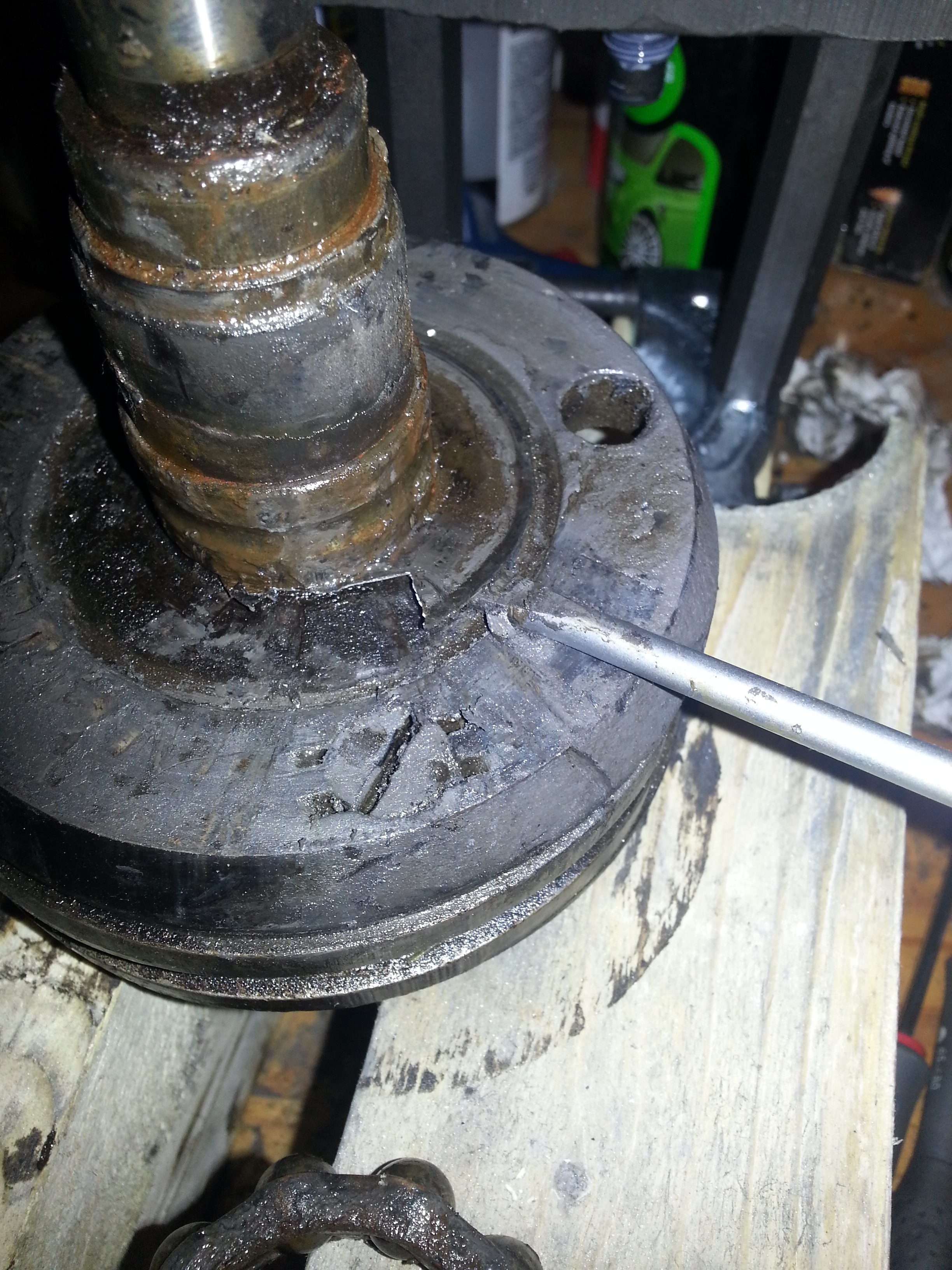
Next we’ll remove the gear shaft bearings; there are two of them; heat up the housing using a heat gun to 80 Celsius and the first bearing will fall out:
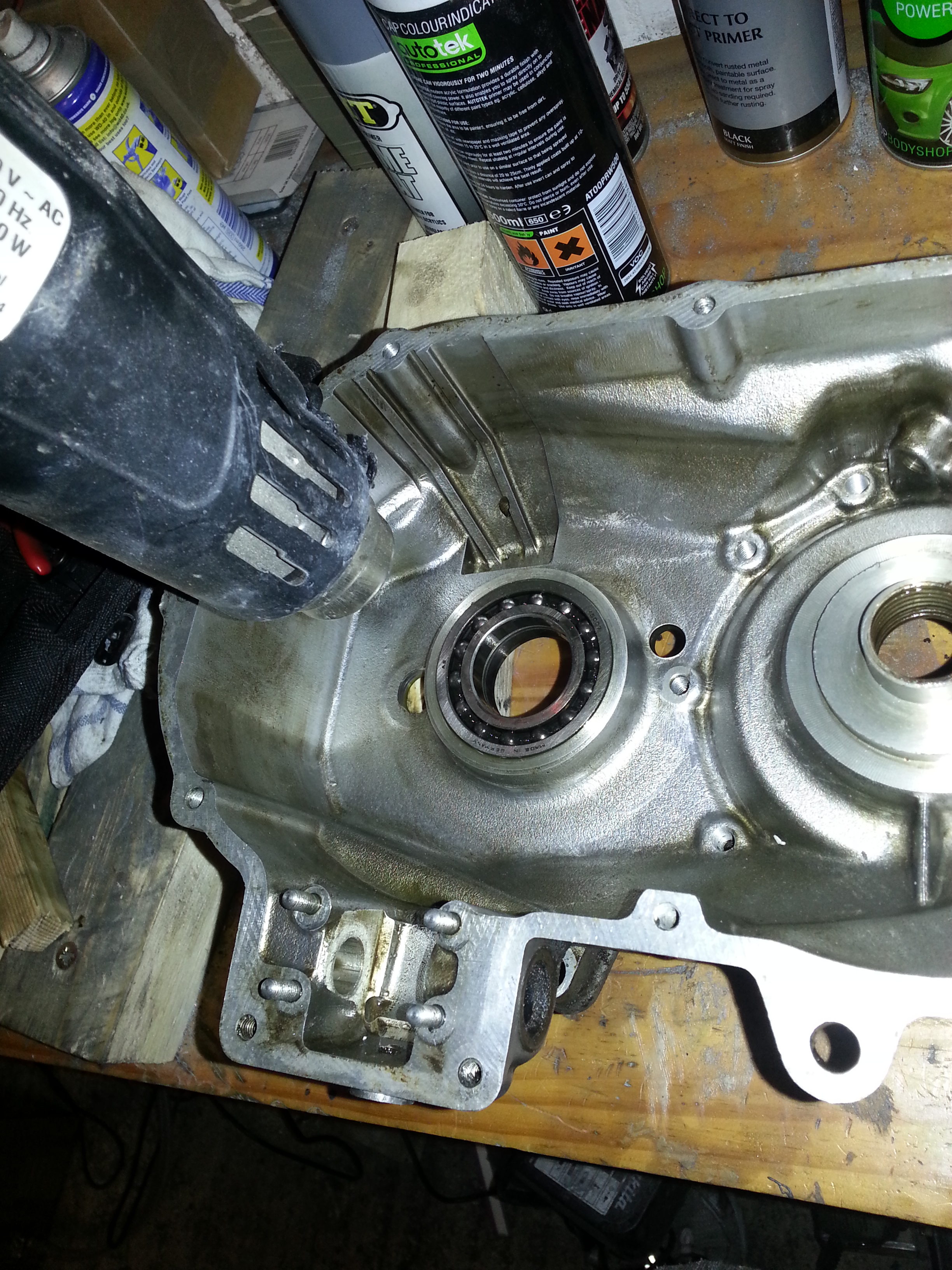
Repeat for the second bearing. We’ll take the gear fork shaft seal out next using a blind bearing puller:
Followed by the main drive shaft seal (this one may be a bit stuck give its metal outer casing:
Under the oil seal is a circlip which must be removed.
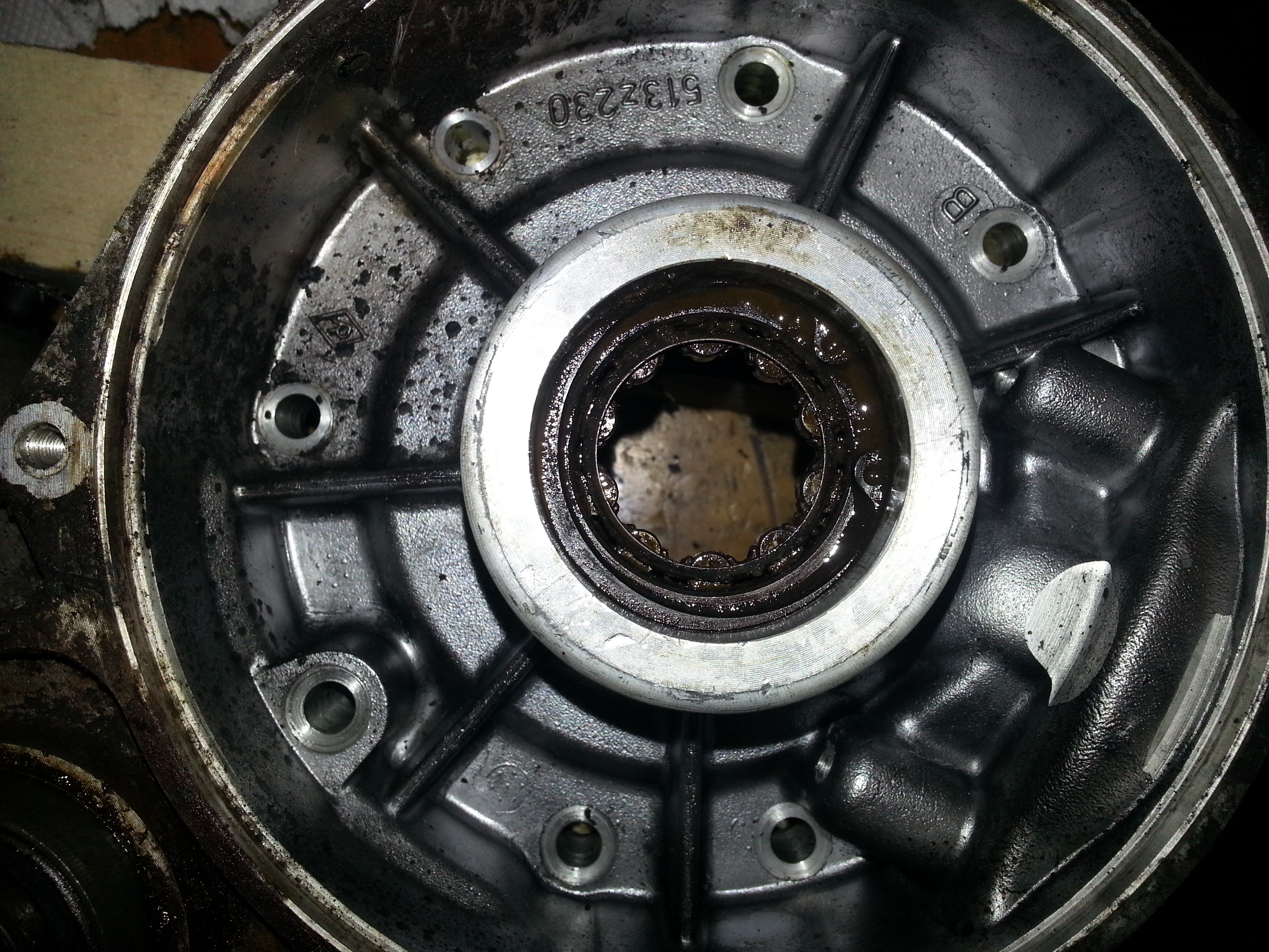
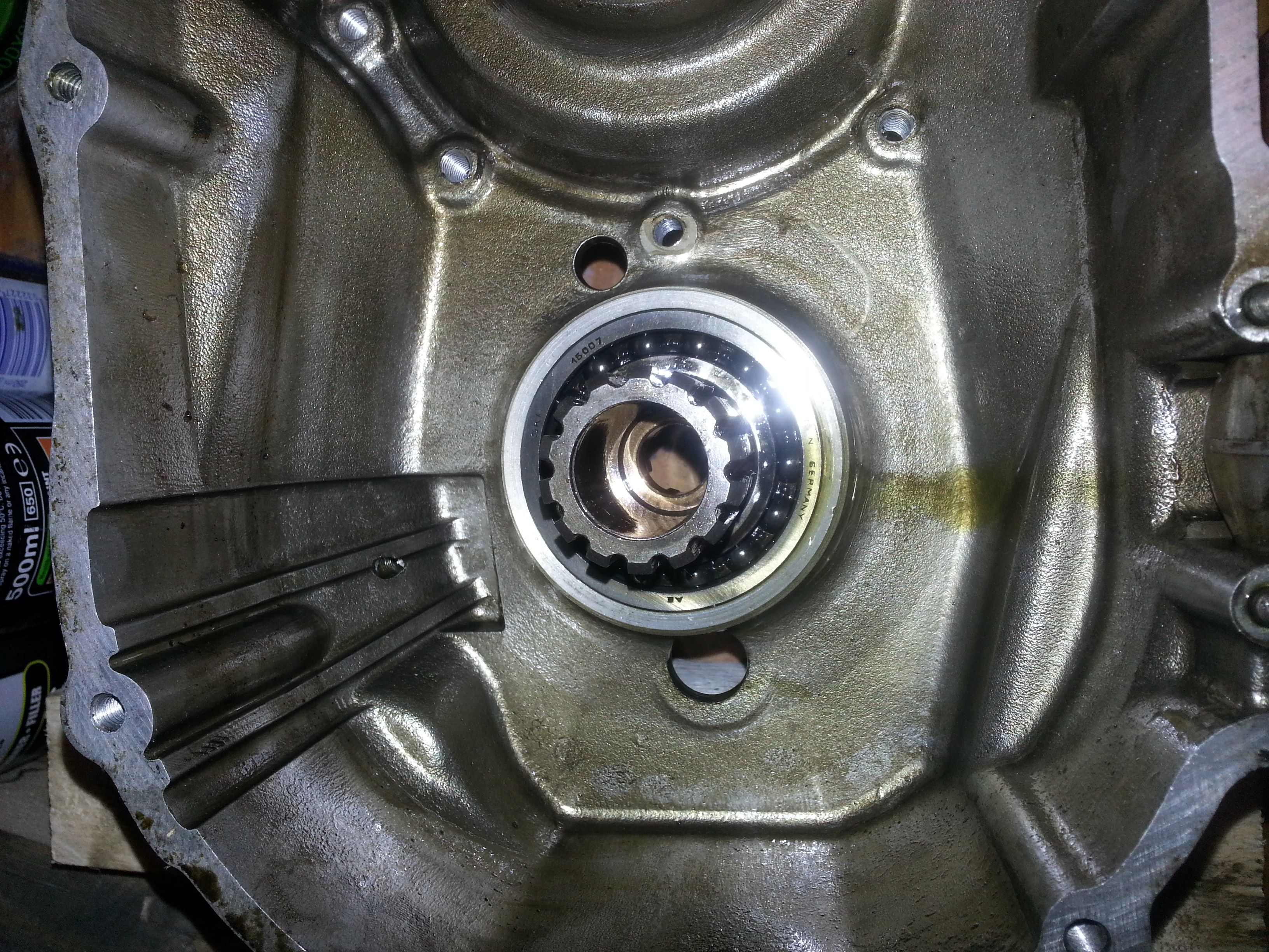
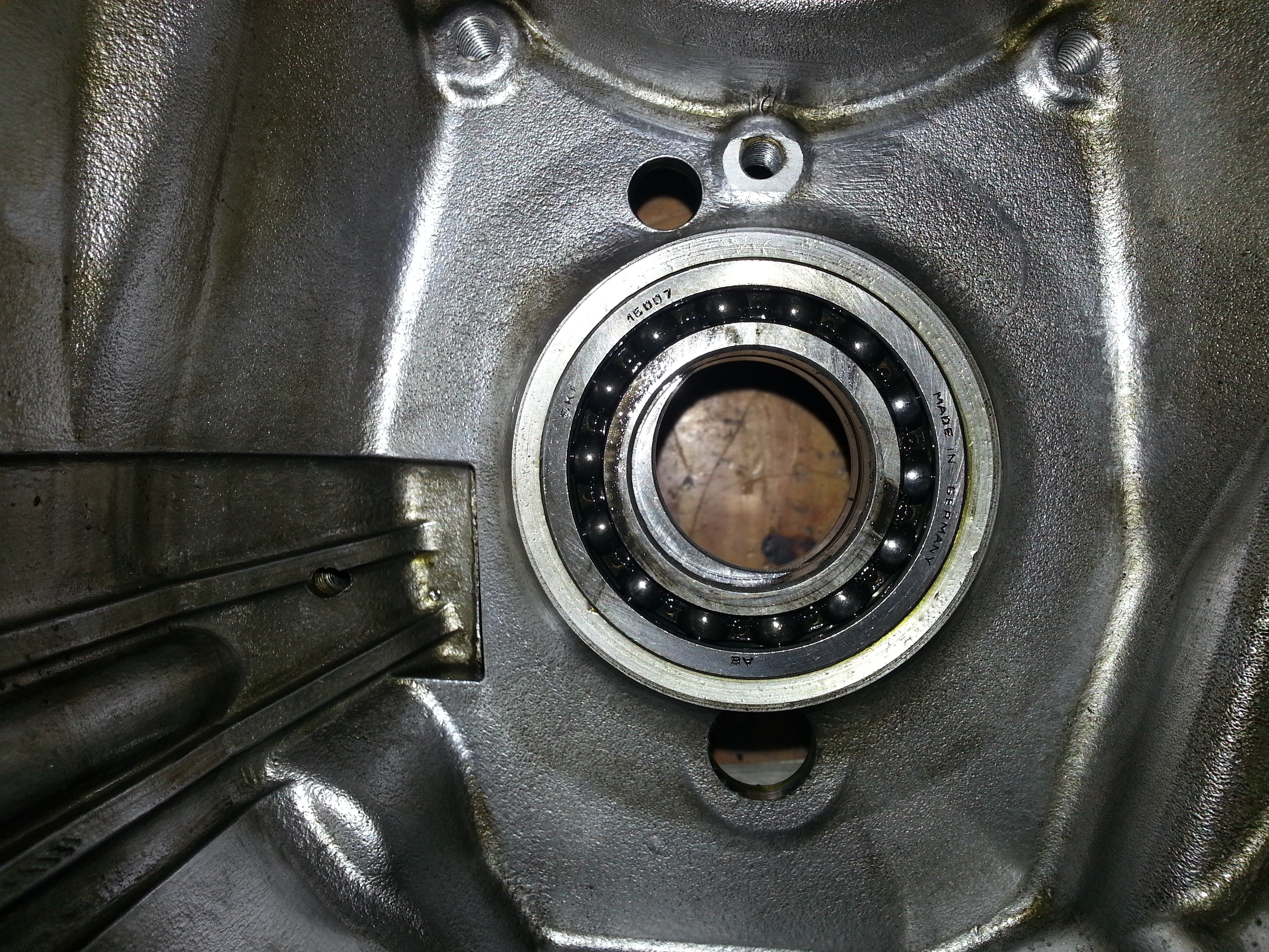
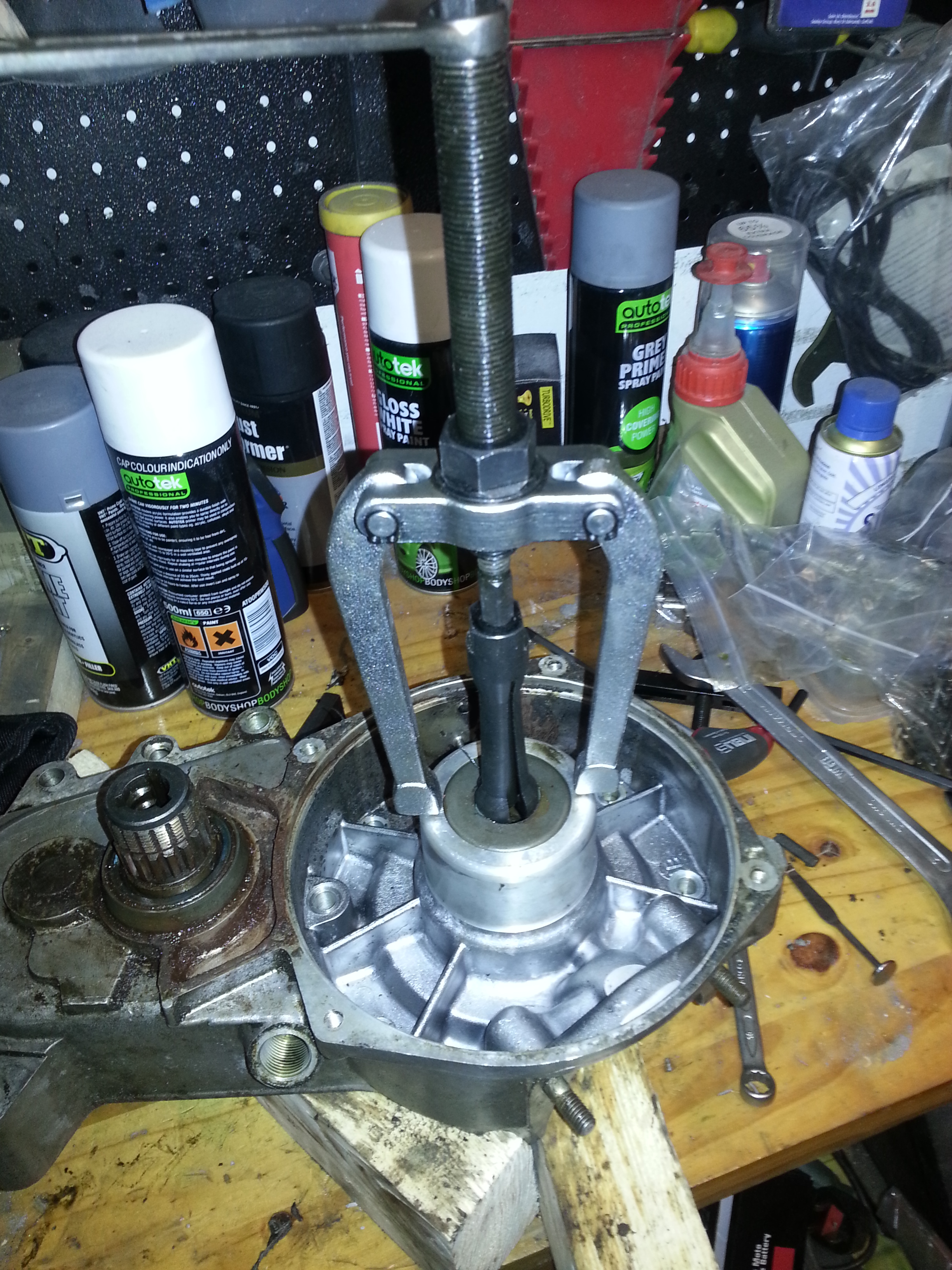
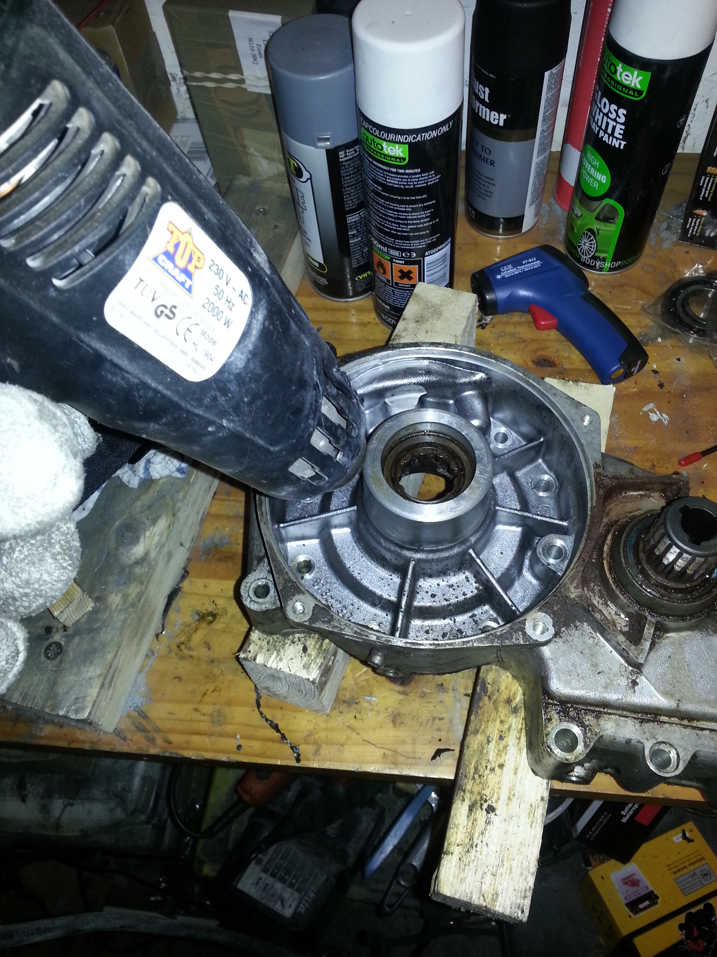
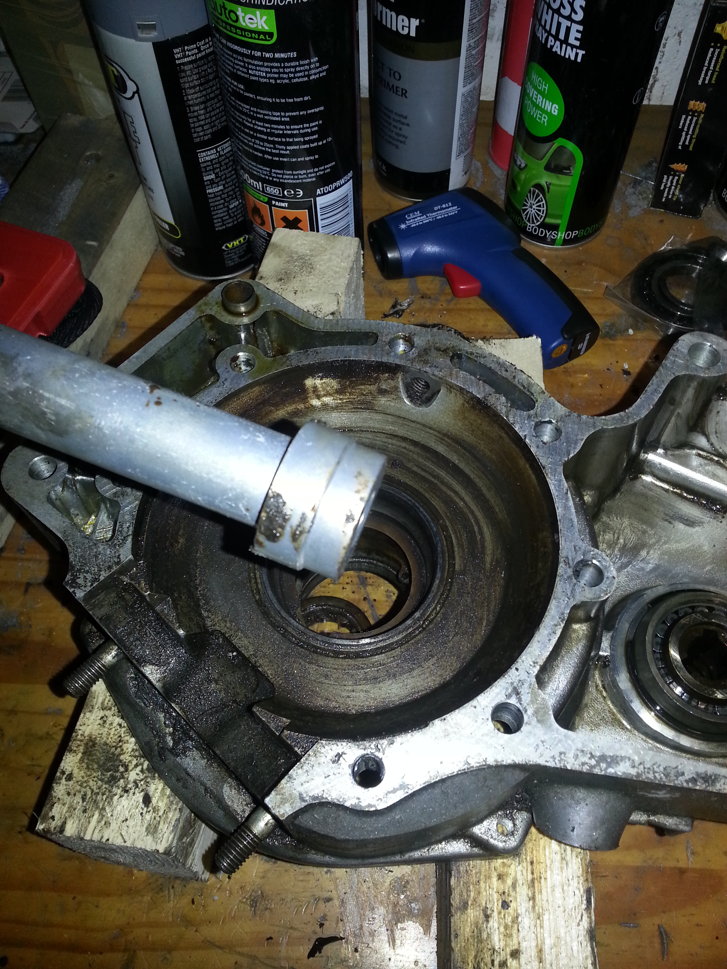
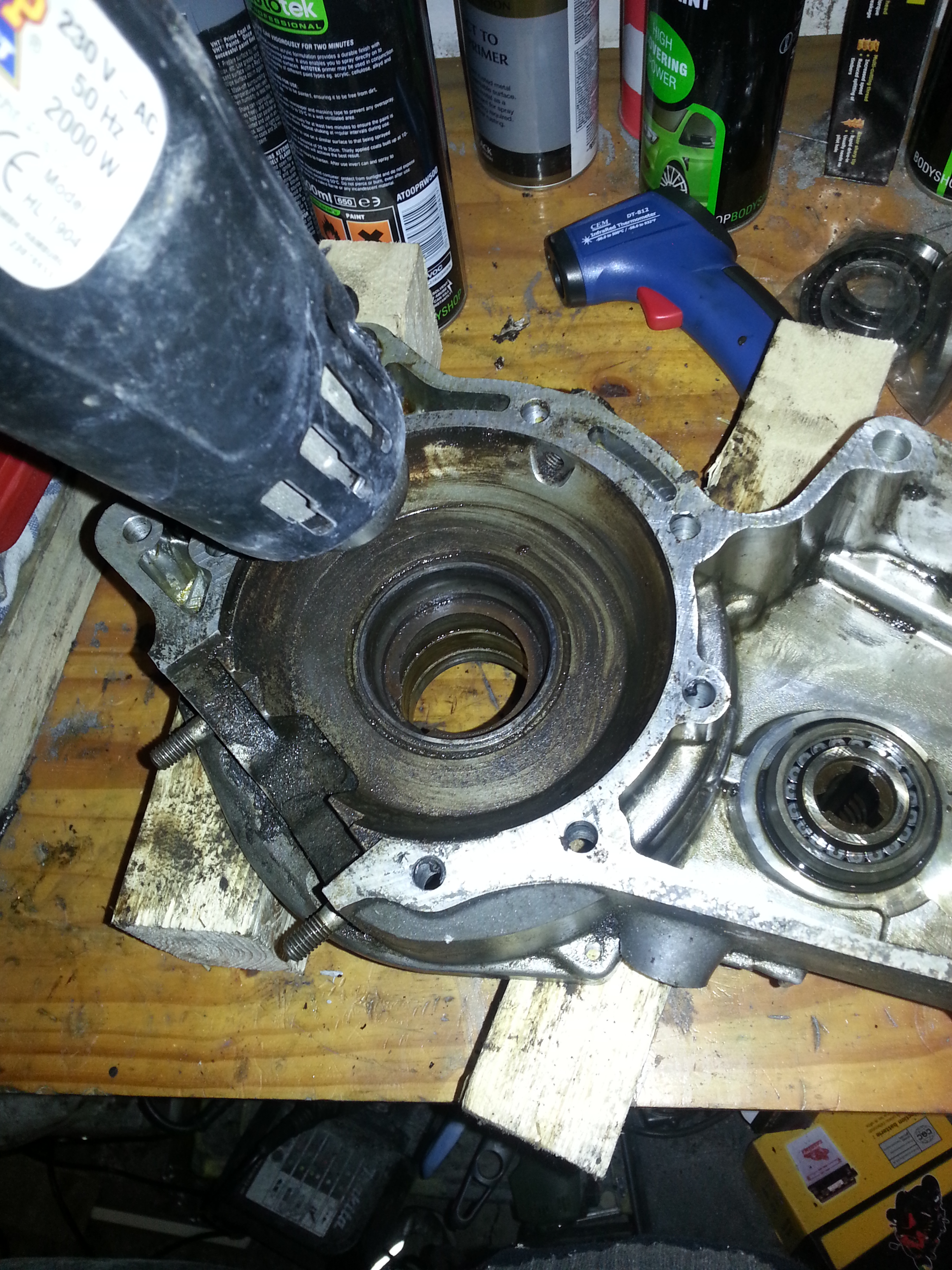
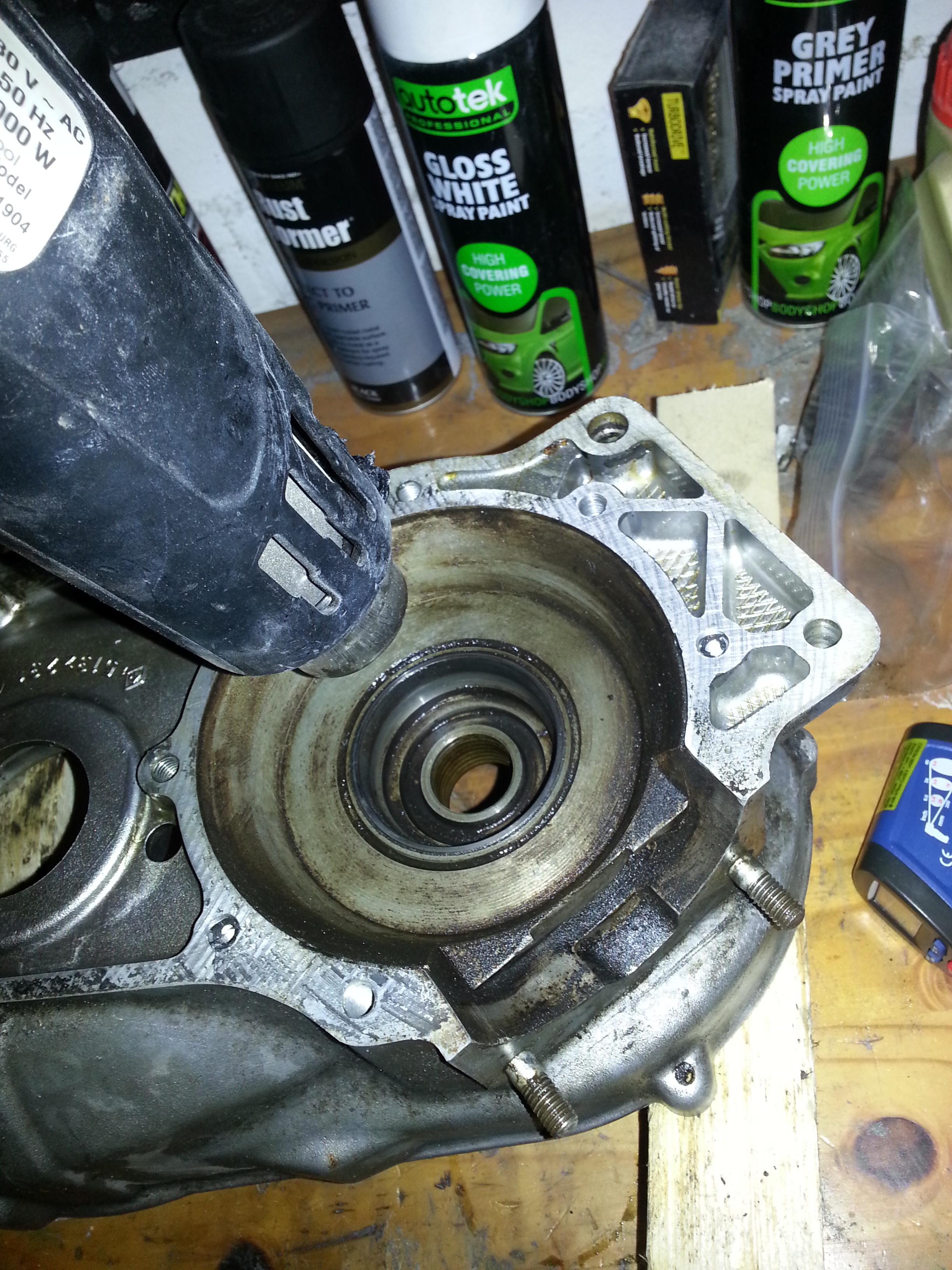
After that, use a heat gun around the bearing underneath to heat the housing to 80 degrees Celsius. Do so by slowly moving the heat gun around the housing. Try not to heat to bearing directly but heat from the outside. The idea is that the housing expanding faster than the bearing will allow for easy removal. Us a temperature reader to make sure you’ve reached the right temperature:
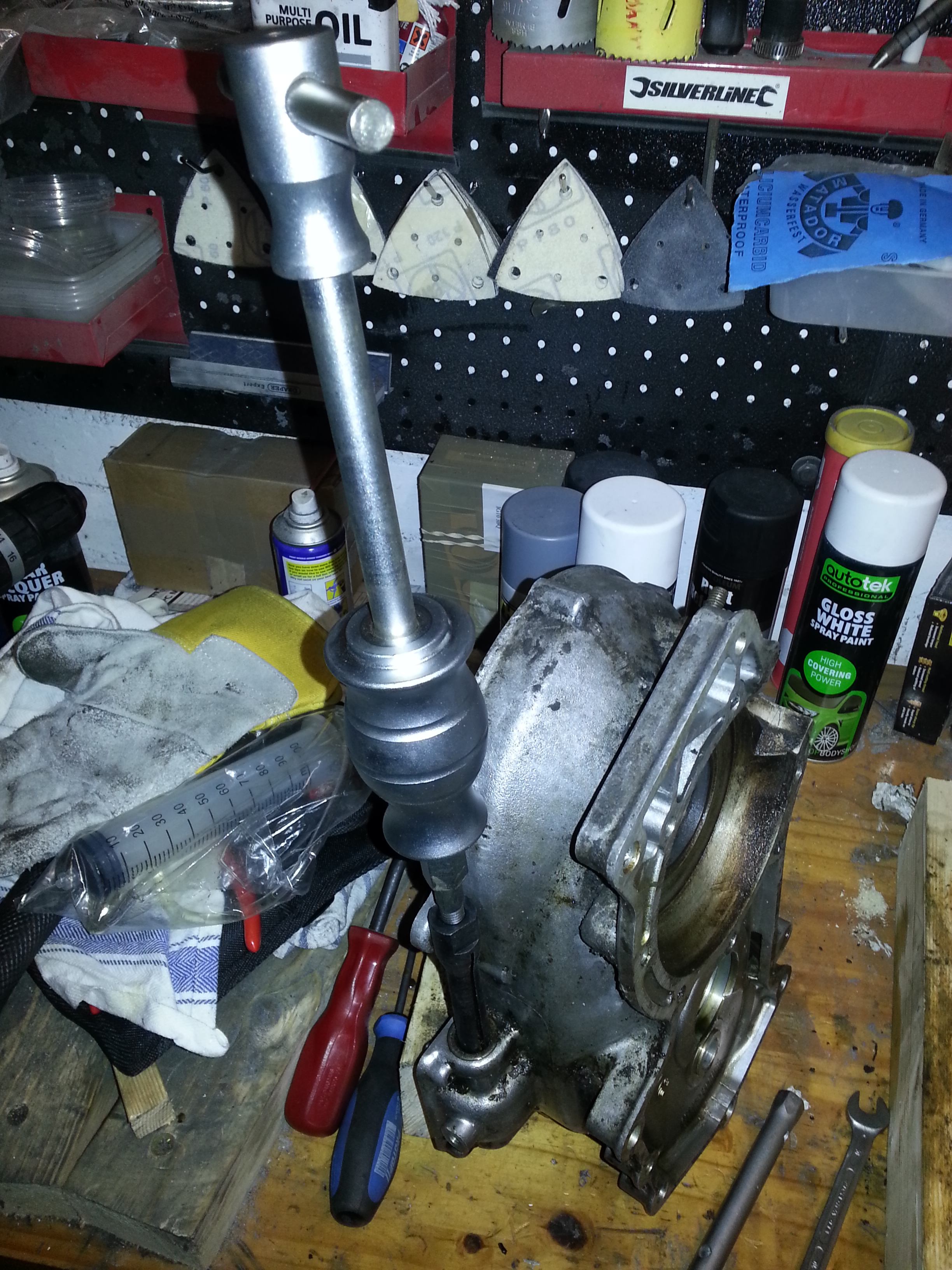
Once the housing has reached the right temparature, turn it around and gently tap the bearing from the other side using a bearing remover:
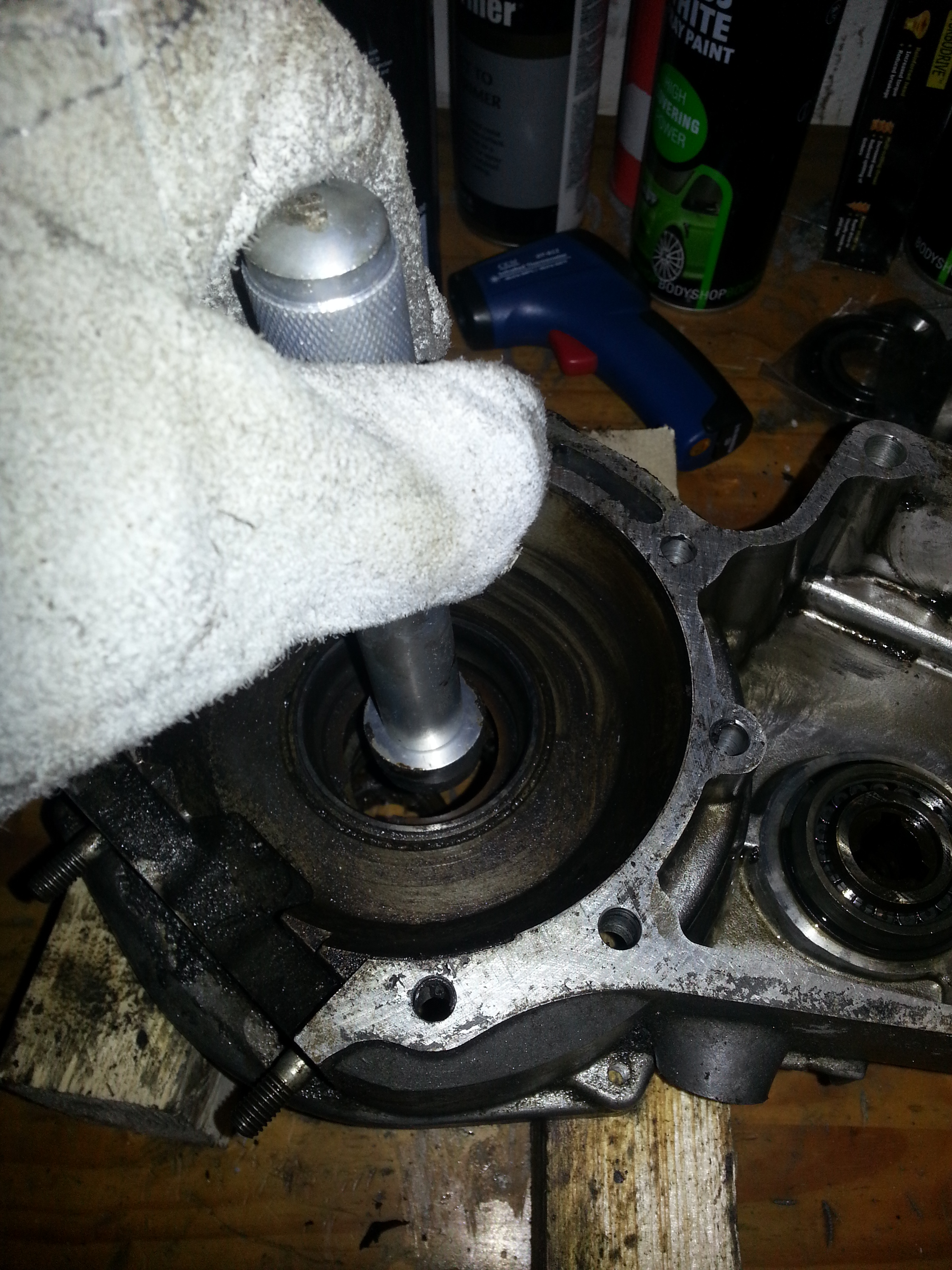
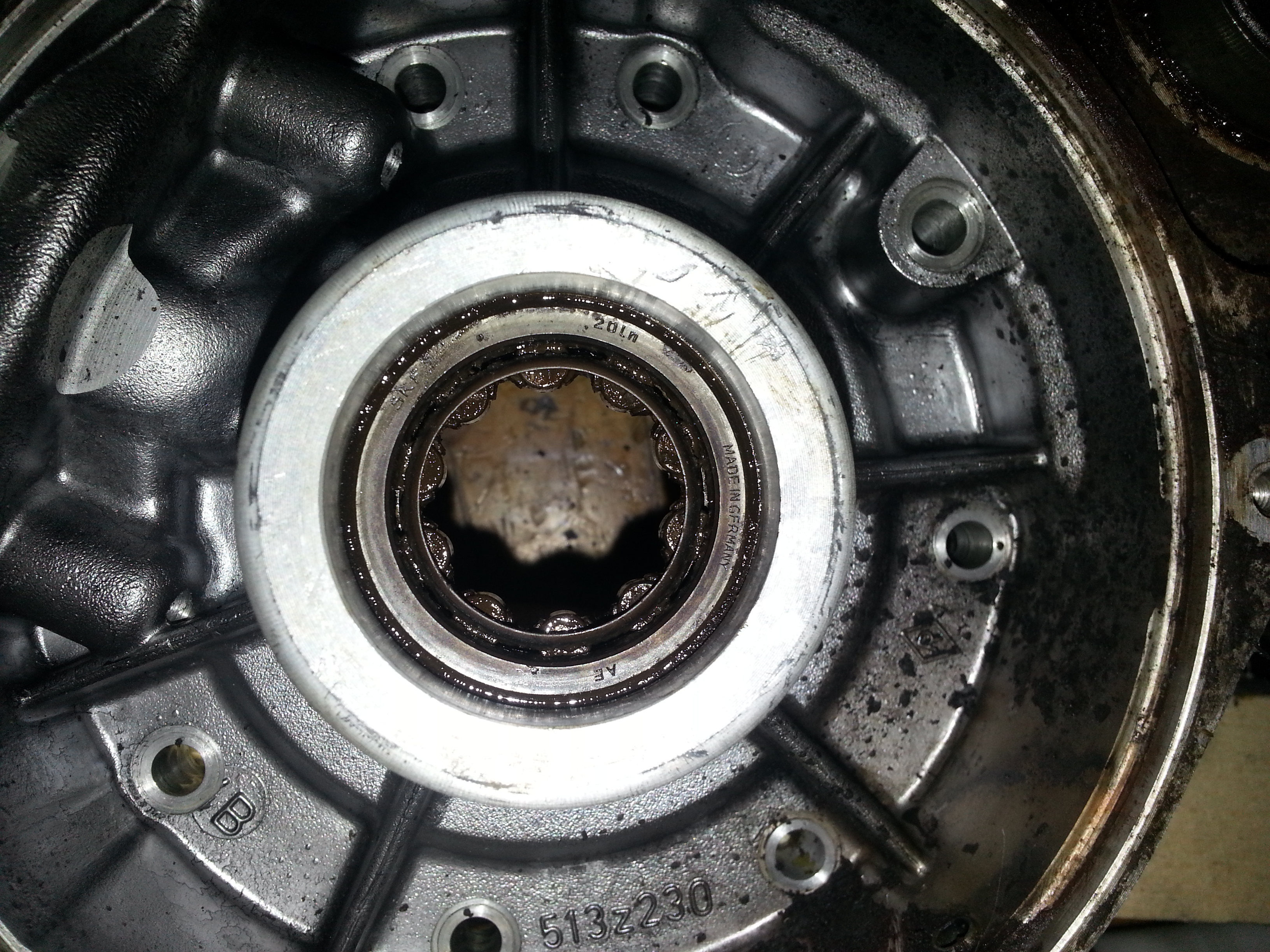
If you heated correctly the bearing should drop out when tapping the engine half on the wooden support blocks or by giving it a gentle tap. Do not use force. The bearing should drop out if the inside of the engine isn’t too rusted:
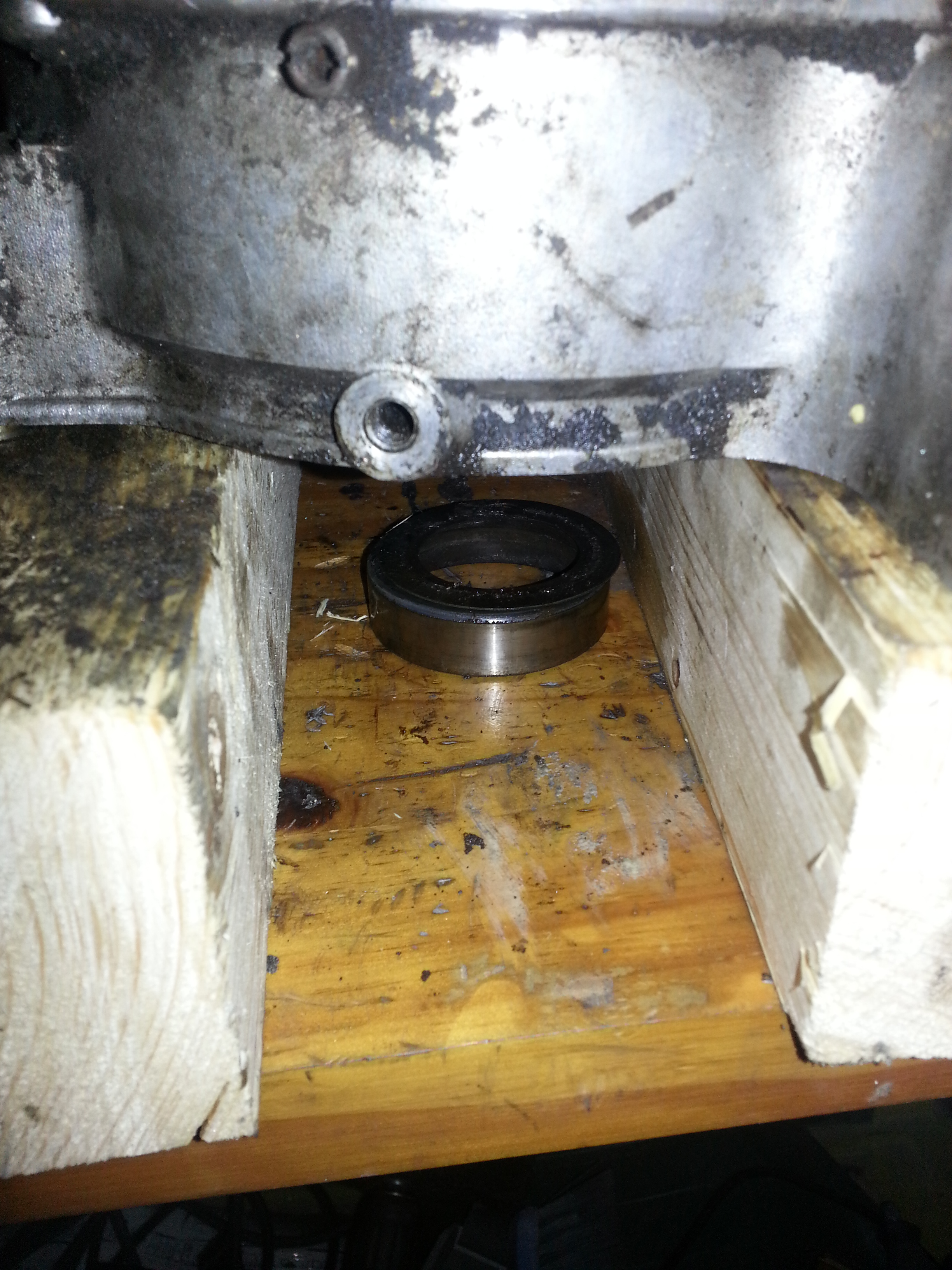
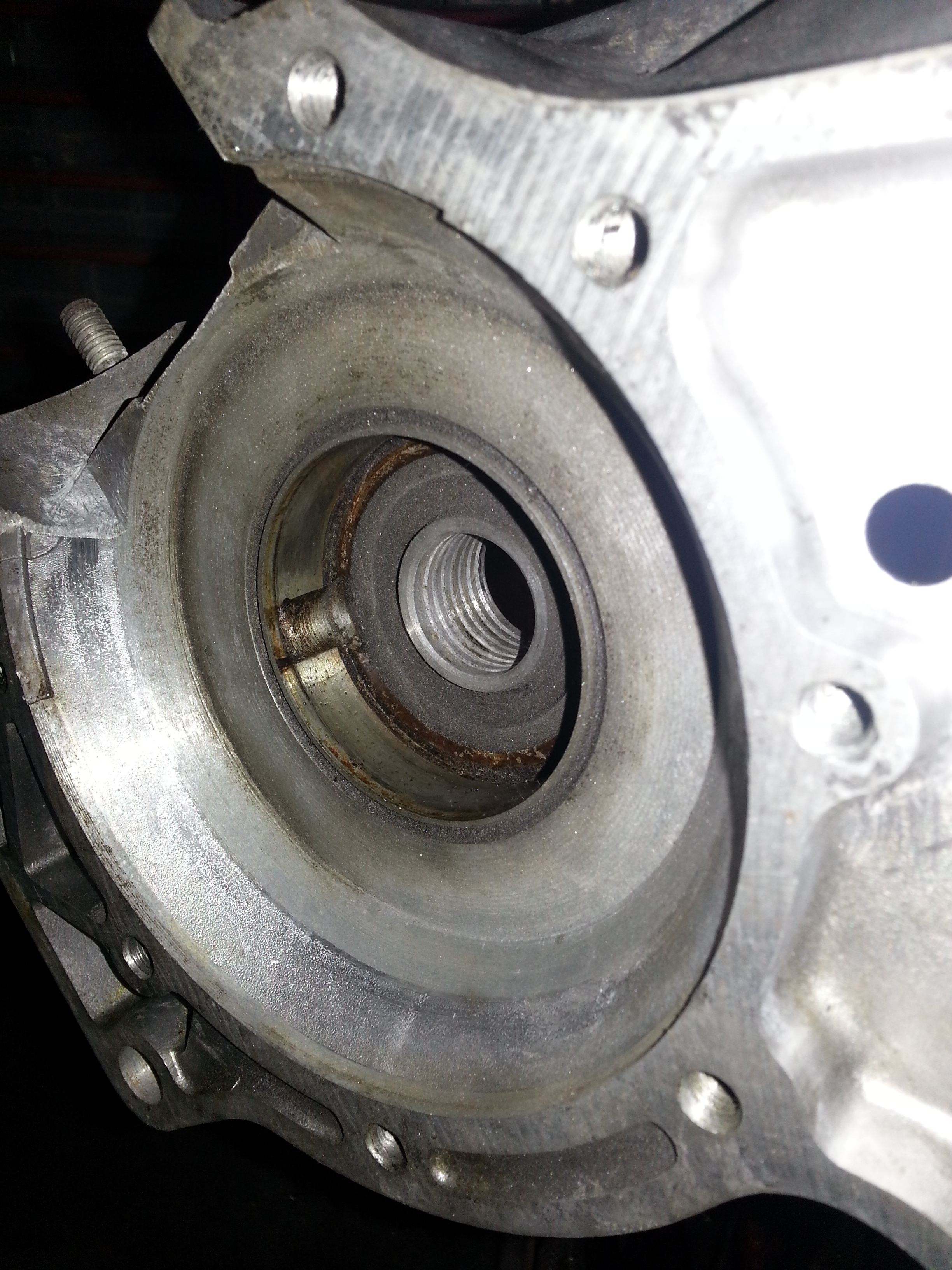
Another circlip that held the bearing in place can be removed next:
You can use the same approach with the two crank bearings. The bearing on one side you can give a very gently tap from the other side (don’t damage the shim washer, it is hard to replace!):
The other engine half will present a problem if it doesn’t drop out by tapping the engine half on a wooden underground:
Luckily, mine dropped out. Otherwise you will have to grind a hold into the bearing housing and try to pull it; not an easy thing to do though; this is the reason we do them first as you they are critical to overhauling the engine.
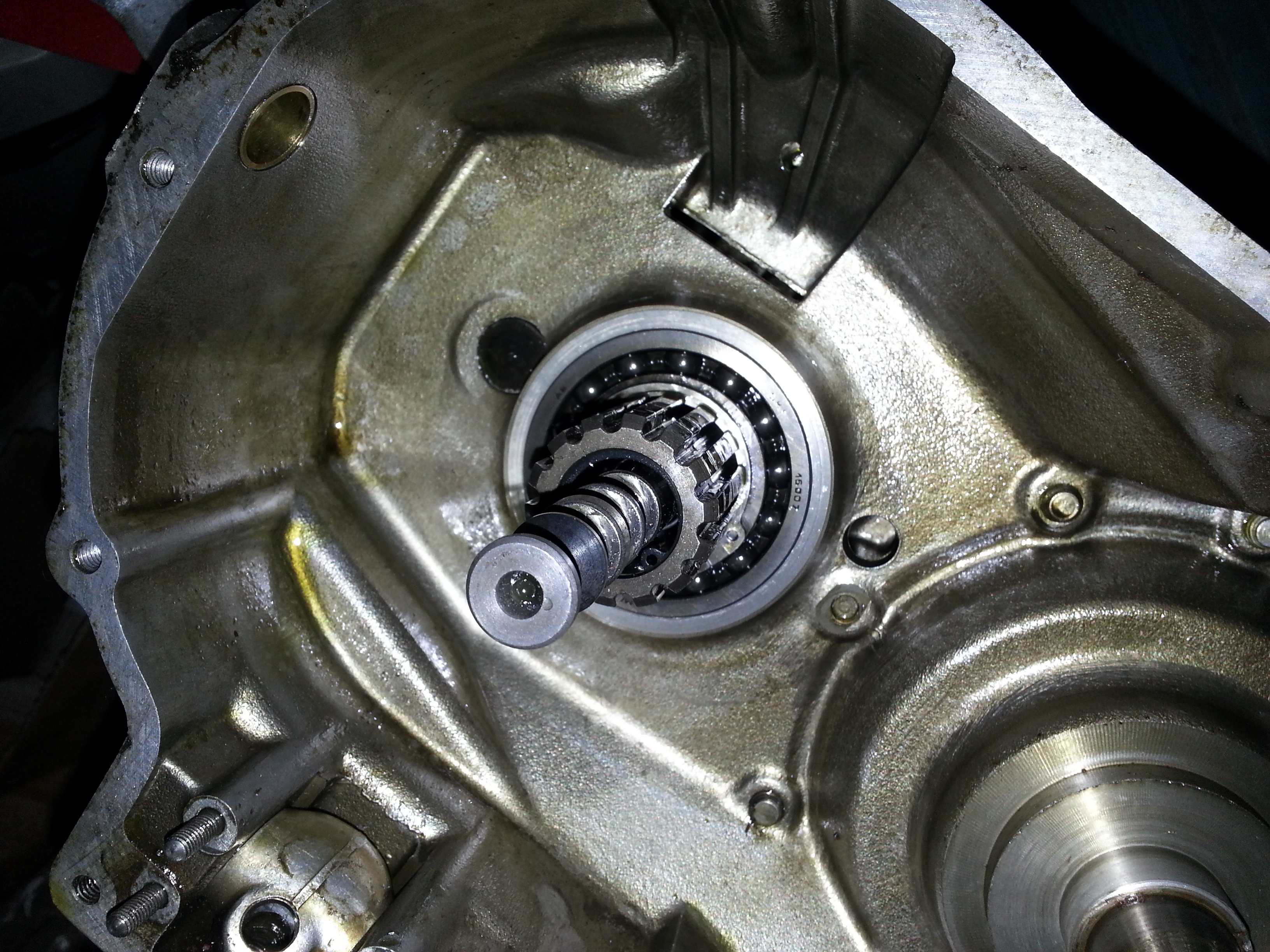
That leaves the final drives shaft bearing:
As this is a custom bearing I would suggest to leave well enough alone unless there is noticeable play in the bearing. You will have replace it with a second hand version, manufacture a new one or replace the roller bearings with a larger version after increasing the bore; none of them a great prospect so fingers crossed it still works as it should. The other challenge here is to remove the oil seal. In the end I had to build a custom oil seal puller to remove it. There is an instruction in the the tools ‘n tips section.
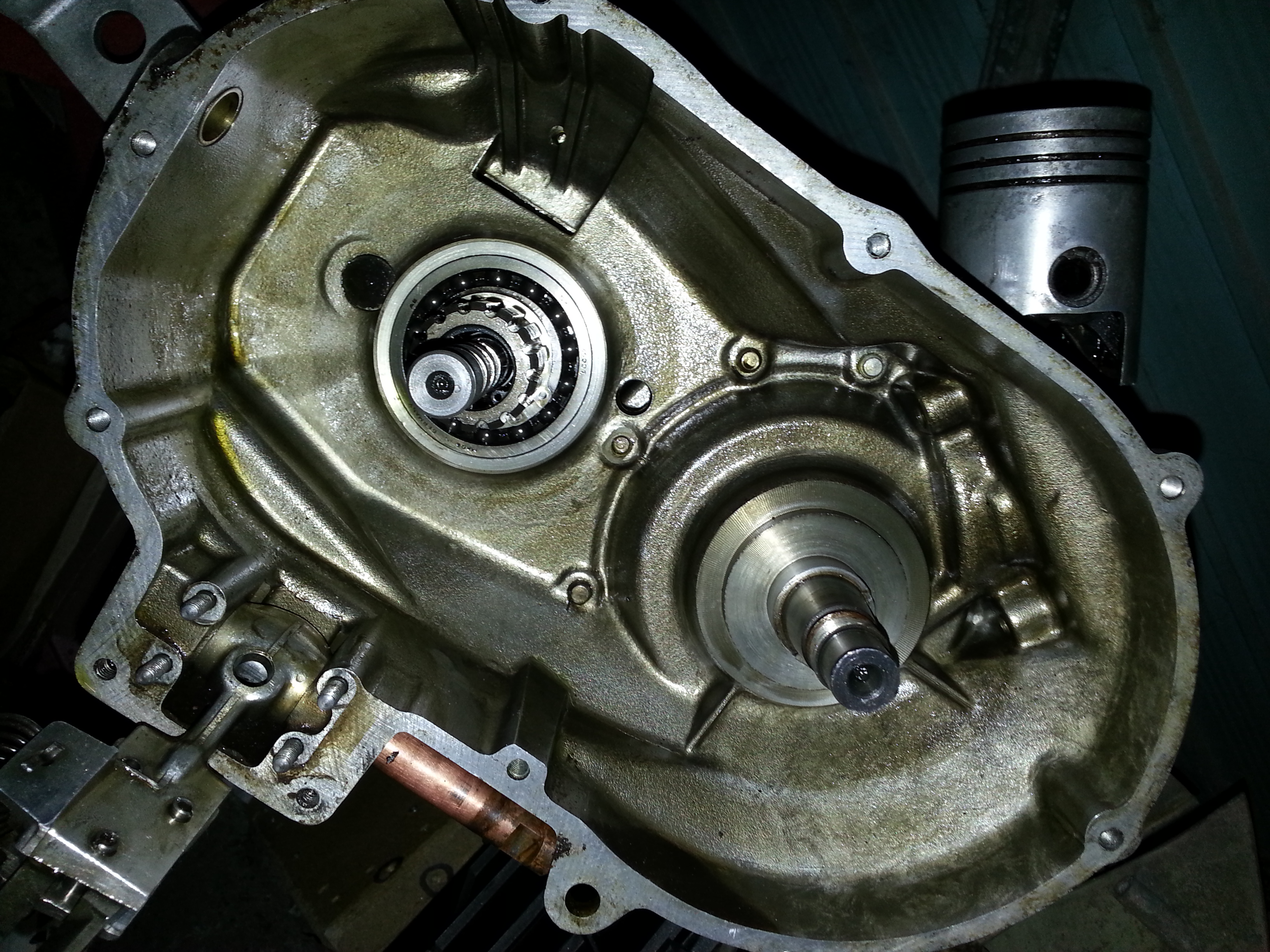
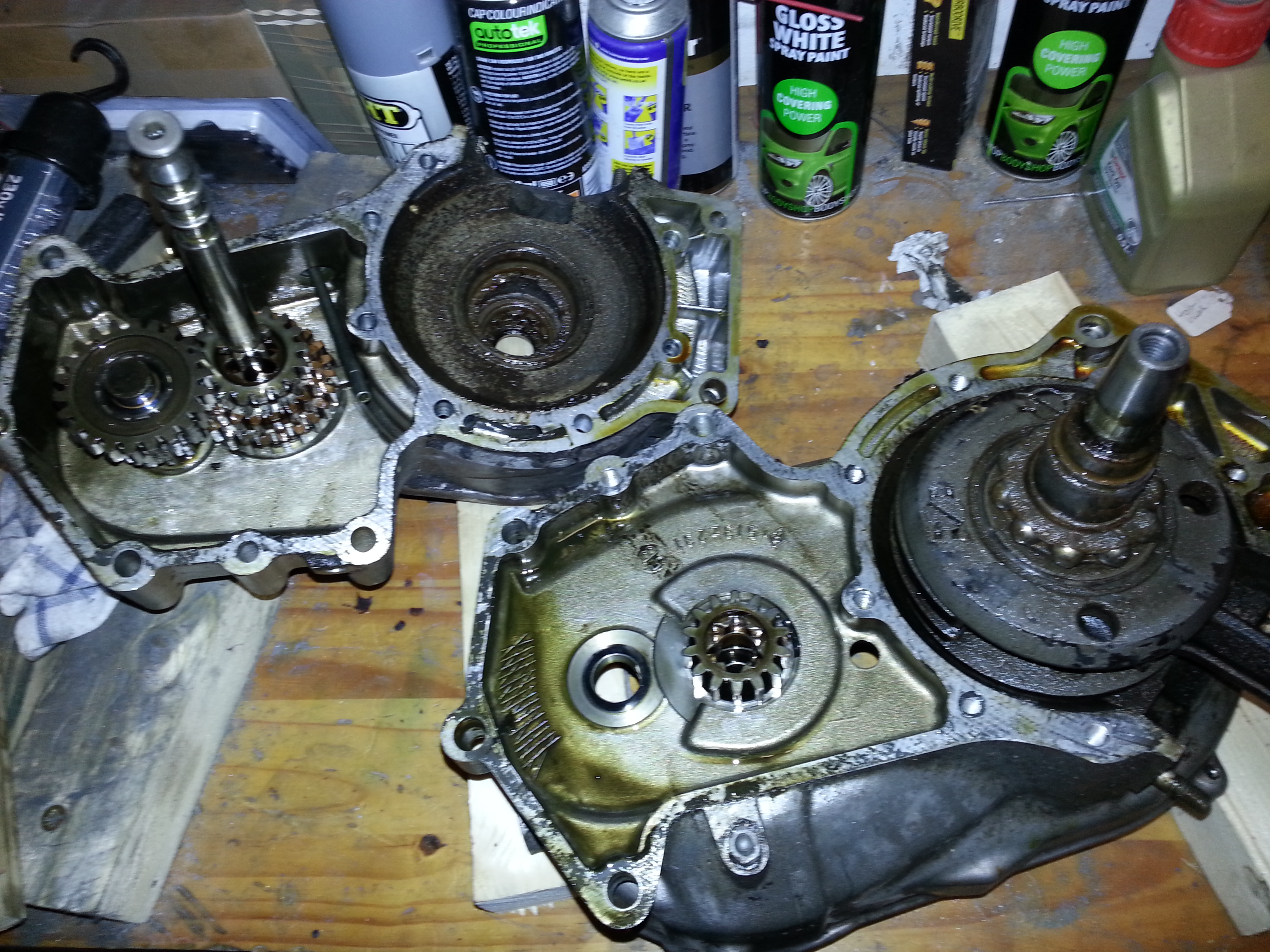
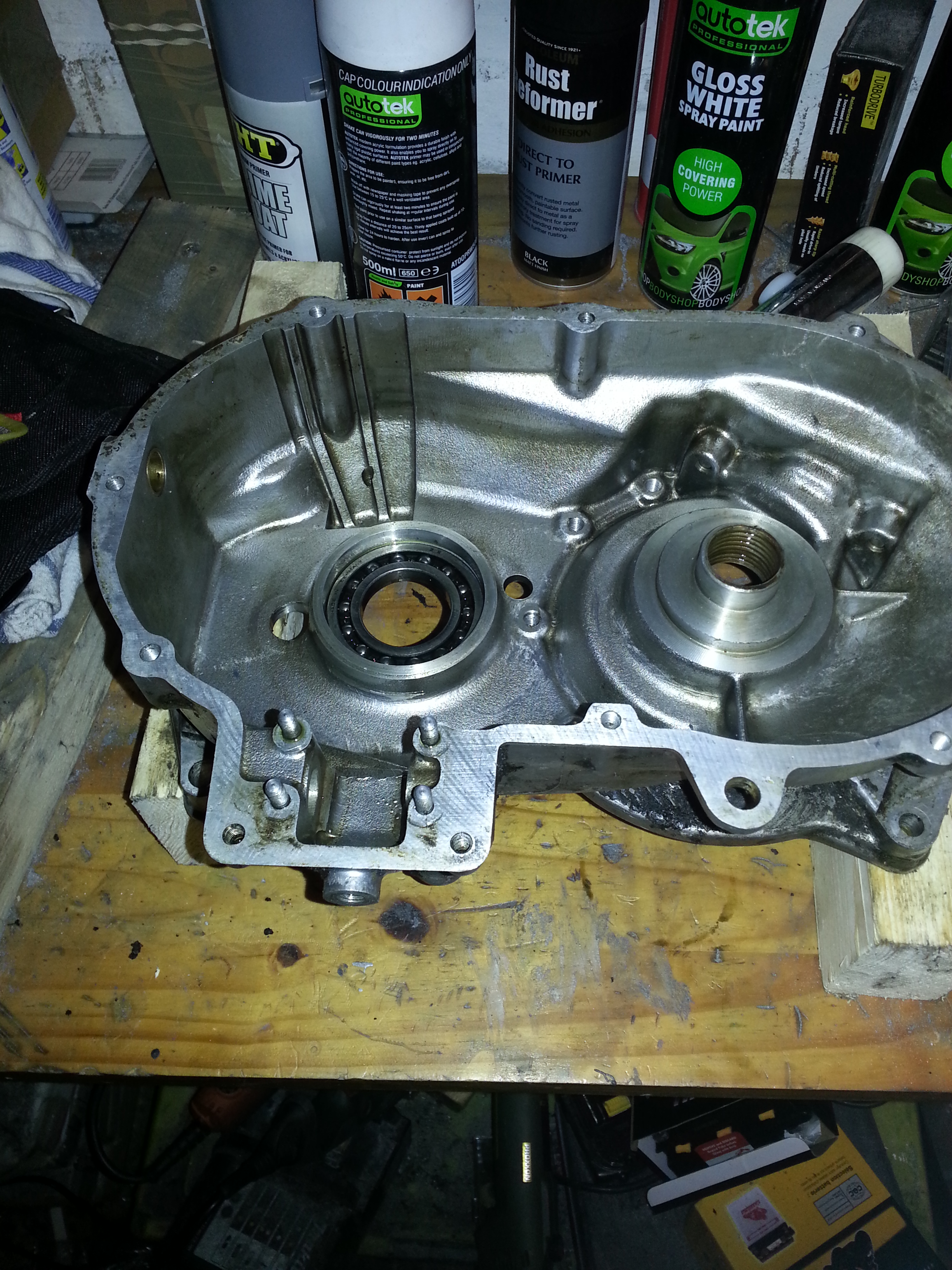
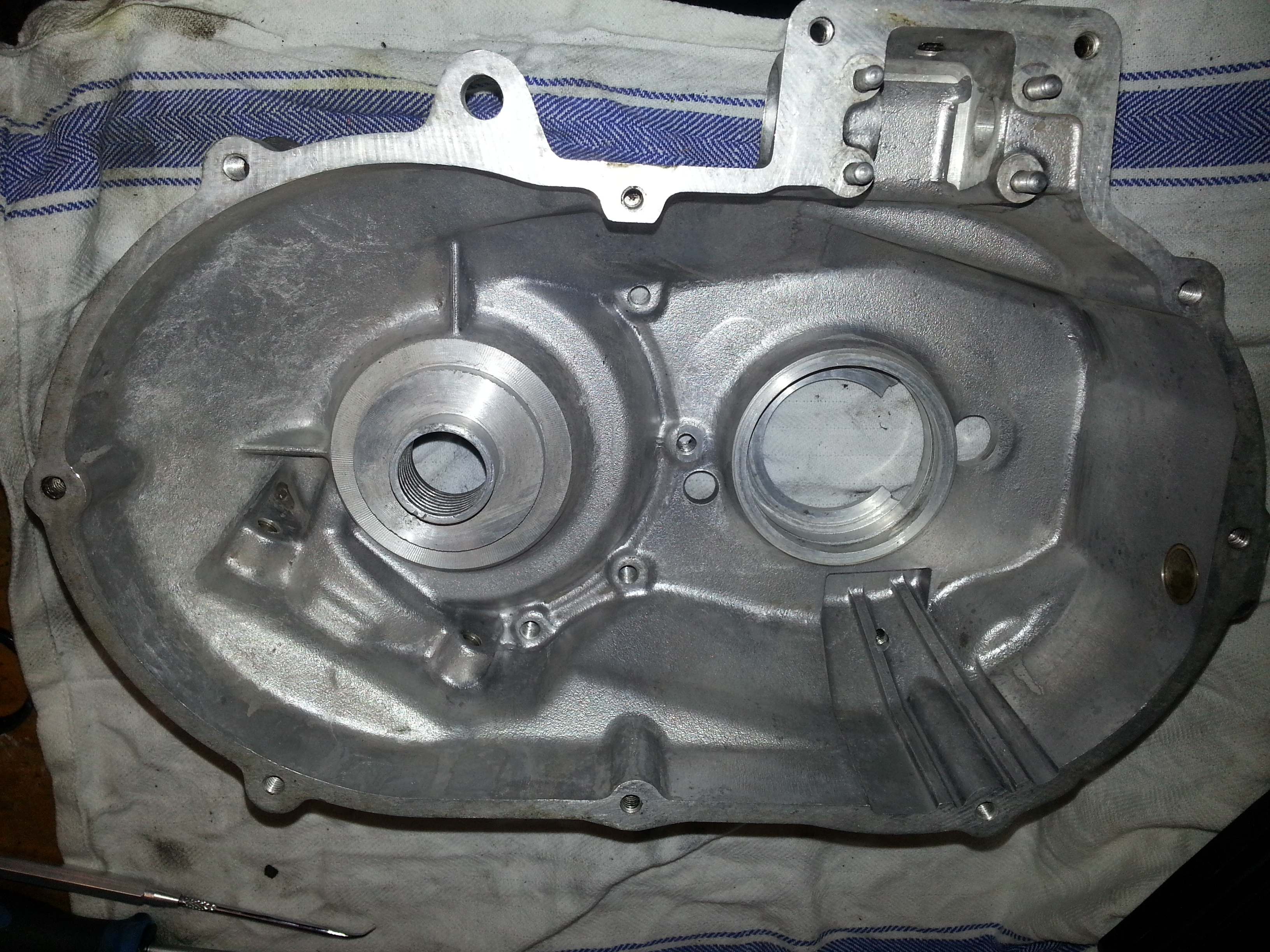
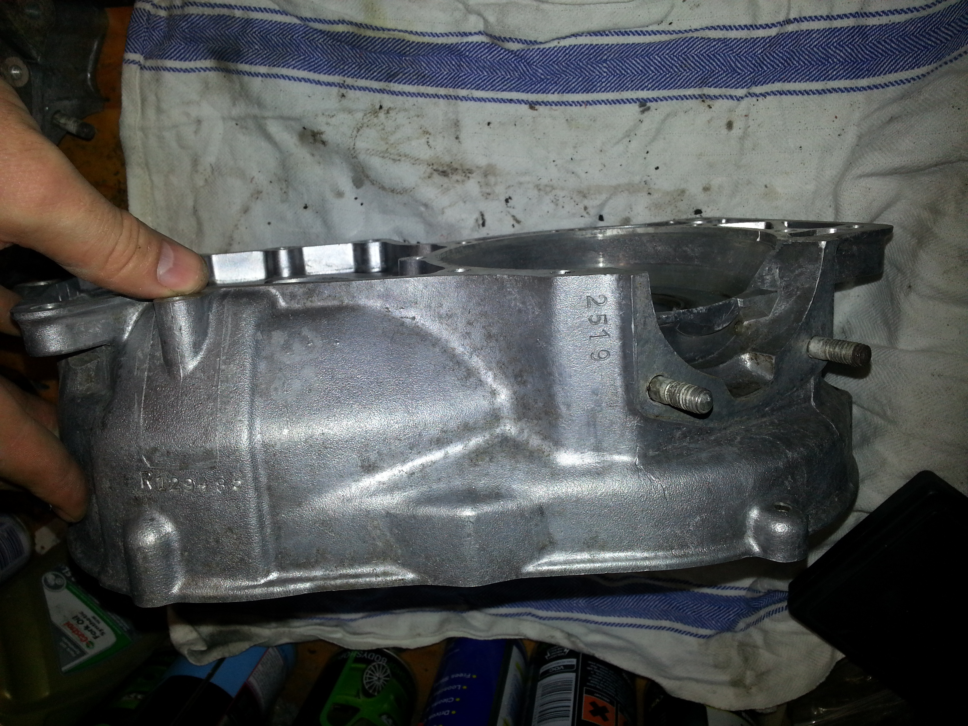
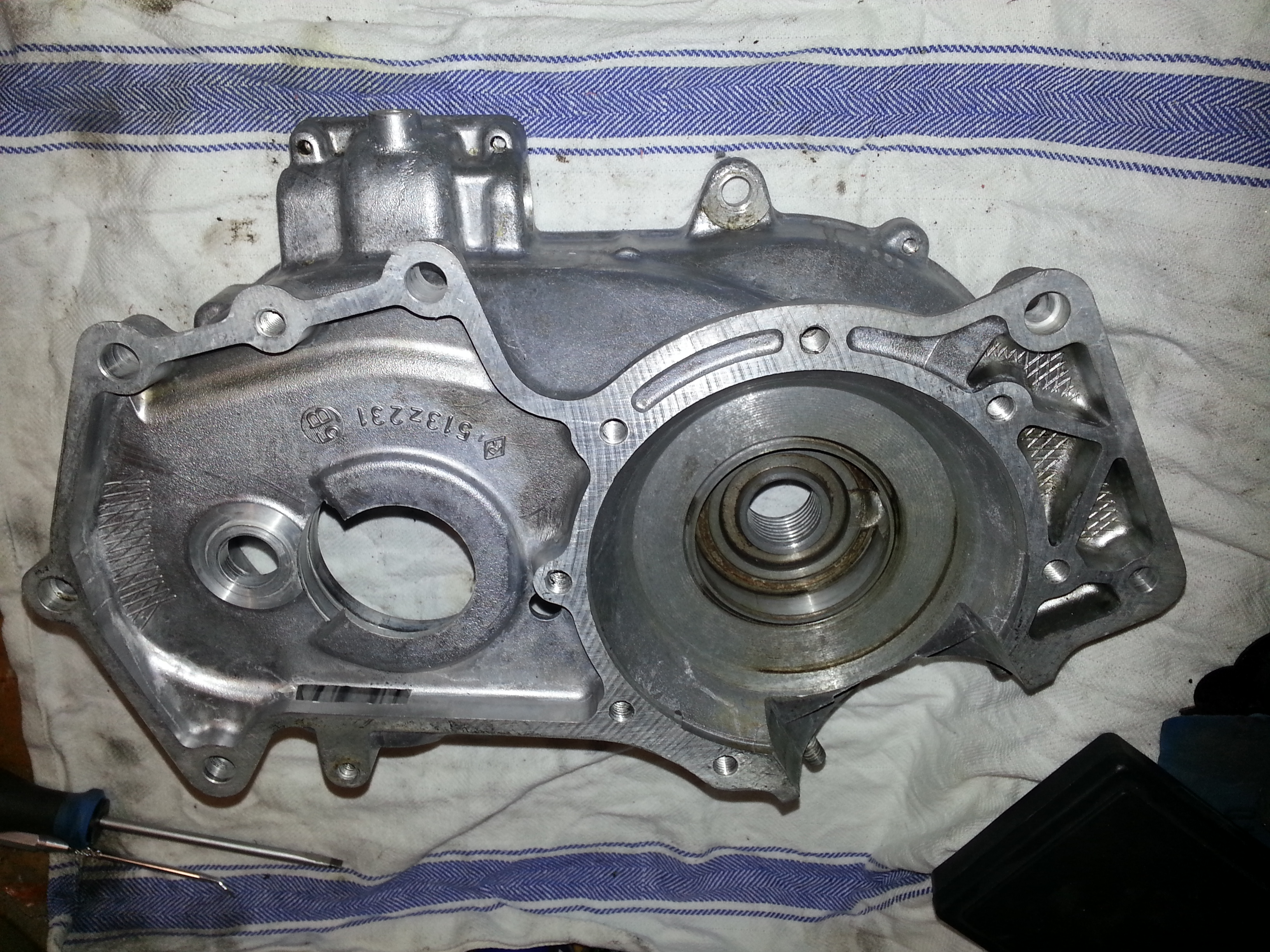
After some cleaning the engine halves are ready for re-assembly:
The final push is the crack. Let’s take it apart too. We’ll start by removing the inner crank bearing cage:
You will likely damage the washer; it will have to be replaced:
With the cage off, well do the same again on the inner bearing:
And we’re ready:
Repeat for the other side; I managed to not damage the washer there, but will replace anyway.
Unless there are known problems with the crank itself, do not take it apart further. Unless there is play in the connecting rod bearings; leave them alone as they are hard to replace.
Next up: rebuilding the engine!