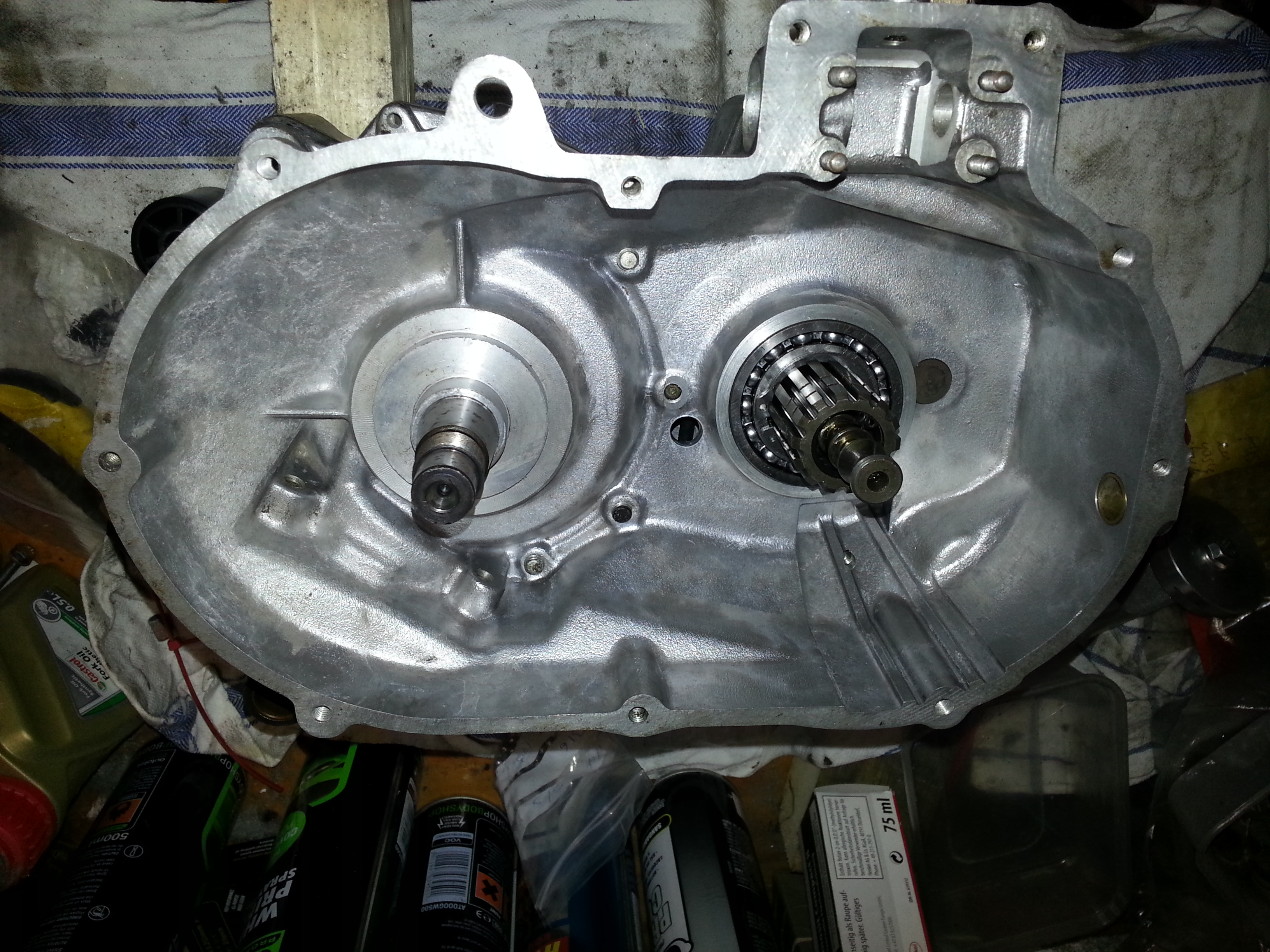
With the two engine halves back together it’s time to install the clutch and the flywheel. A nice task. Let’s start with putting the two engine halves on some blocks of wood so we can work unencumbered:
We can now take the clutch disc stack that we secured previously :
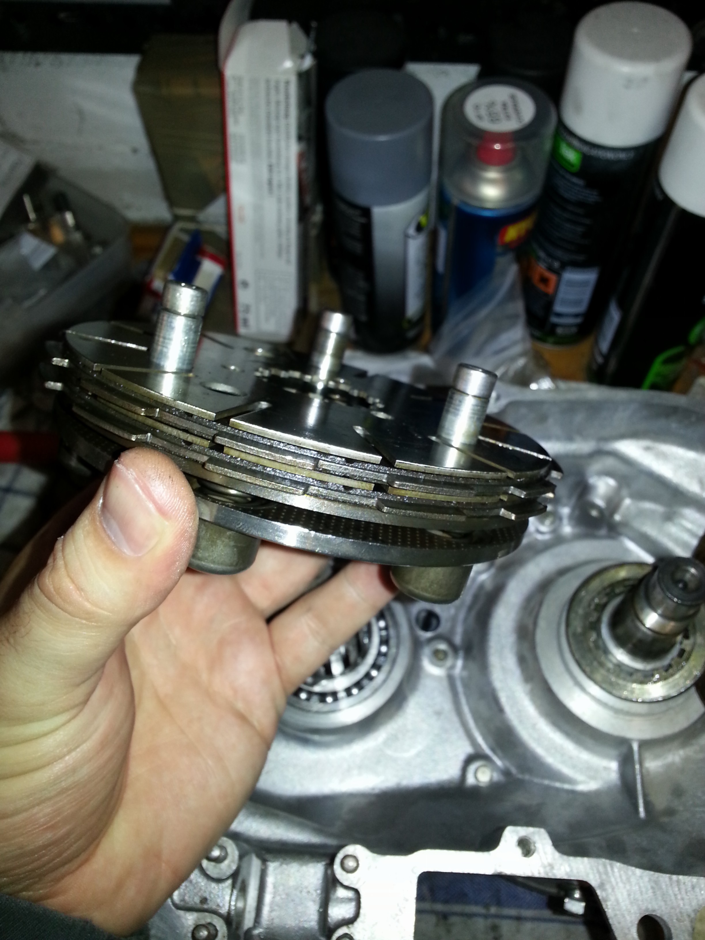
and put it in place:
The orientation of the stack is not important at this time. I must admit that I didn’t check the clutch plates for wear at this time as the speedometer indicates 18.000 miles. The plates should have life in them, but with hindsight I should have checked. Next we put the gearwheel on. This time orientation matters; the clutch pin holes need to remain free when the gearwheel is on. We’ll put it on and align it:
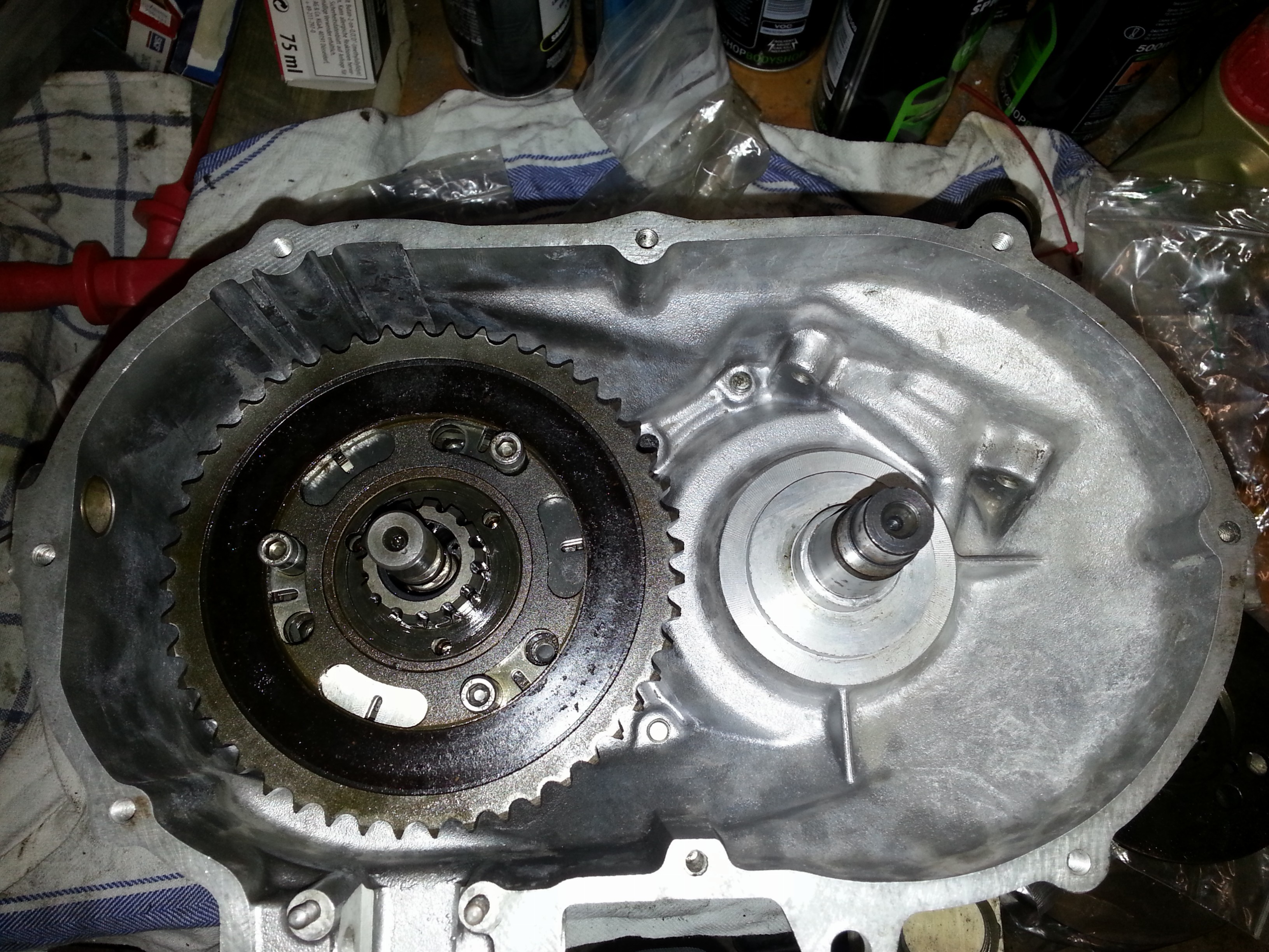
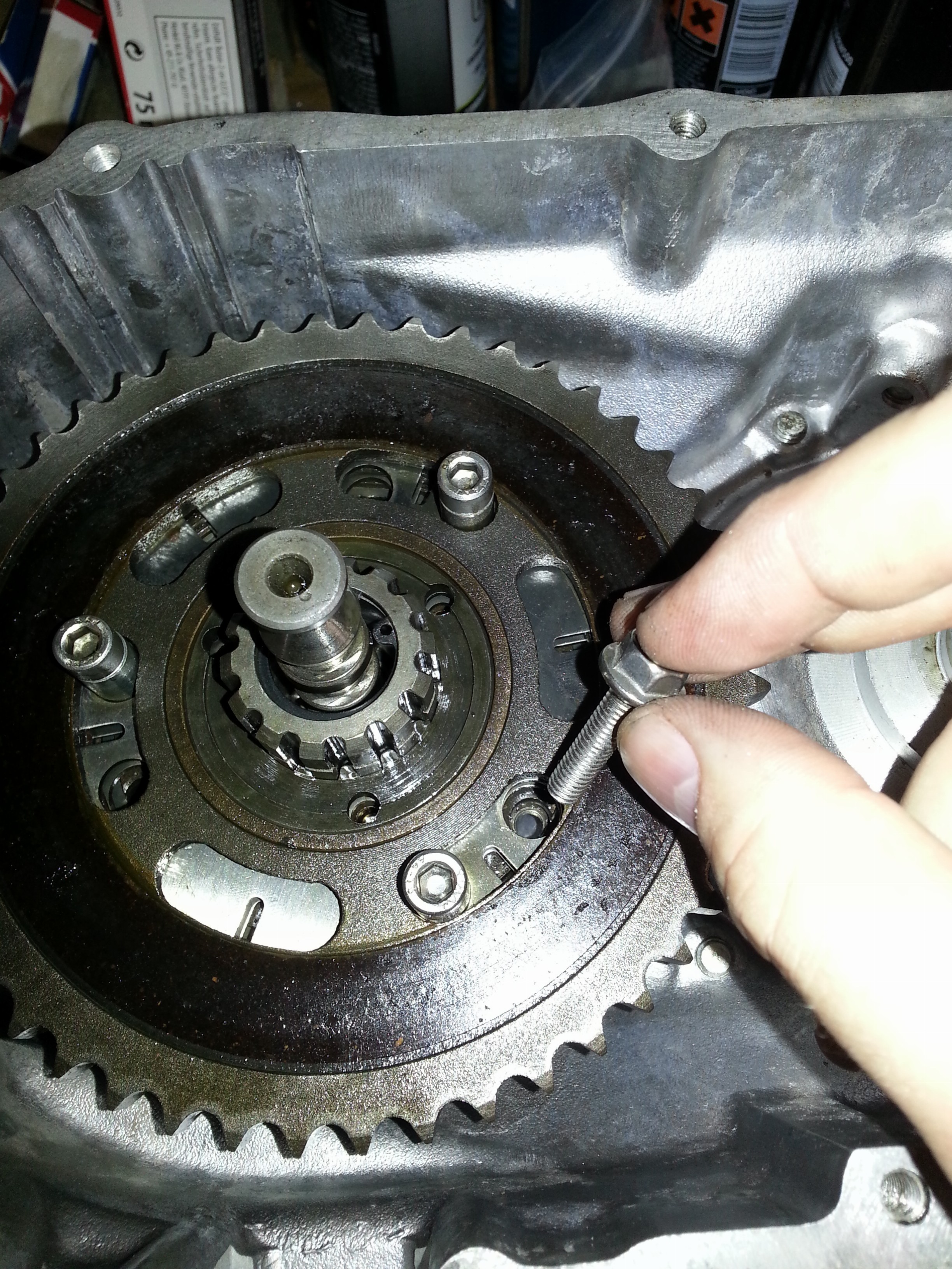
This appears ok; the clutch pin holes remain open, the screws fit and a hole remains open to insert the screw that we can use to ‘freeze’ the gear wheel in place and add a screw so we can lift the stack out in one piece:
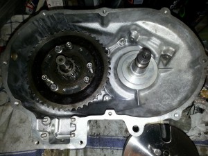
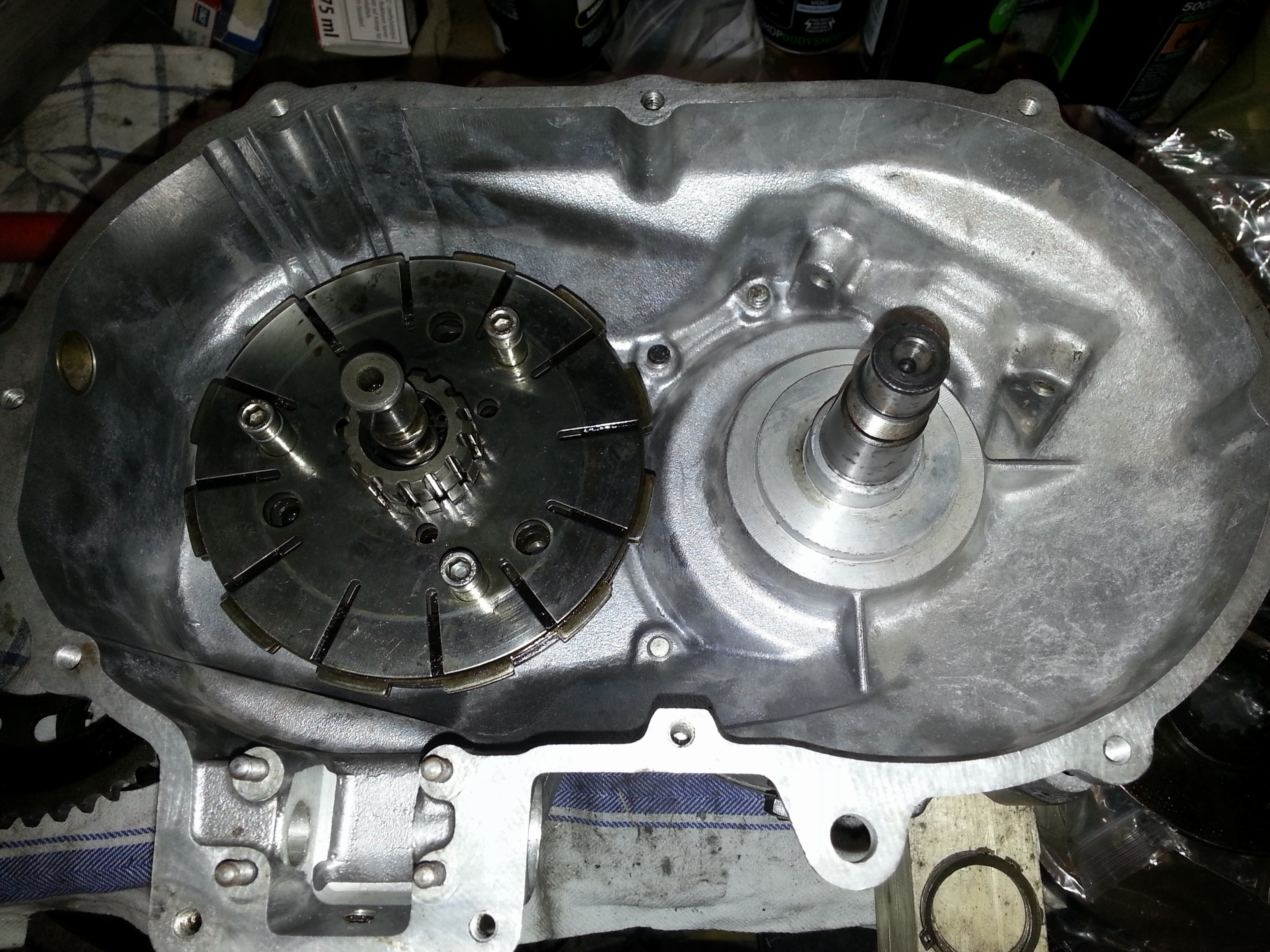
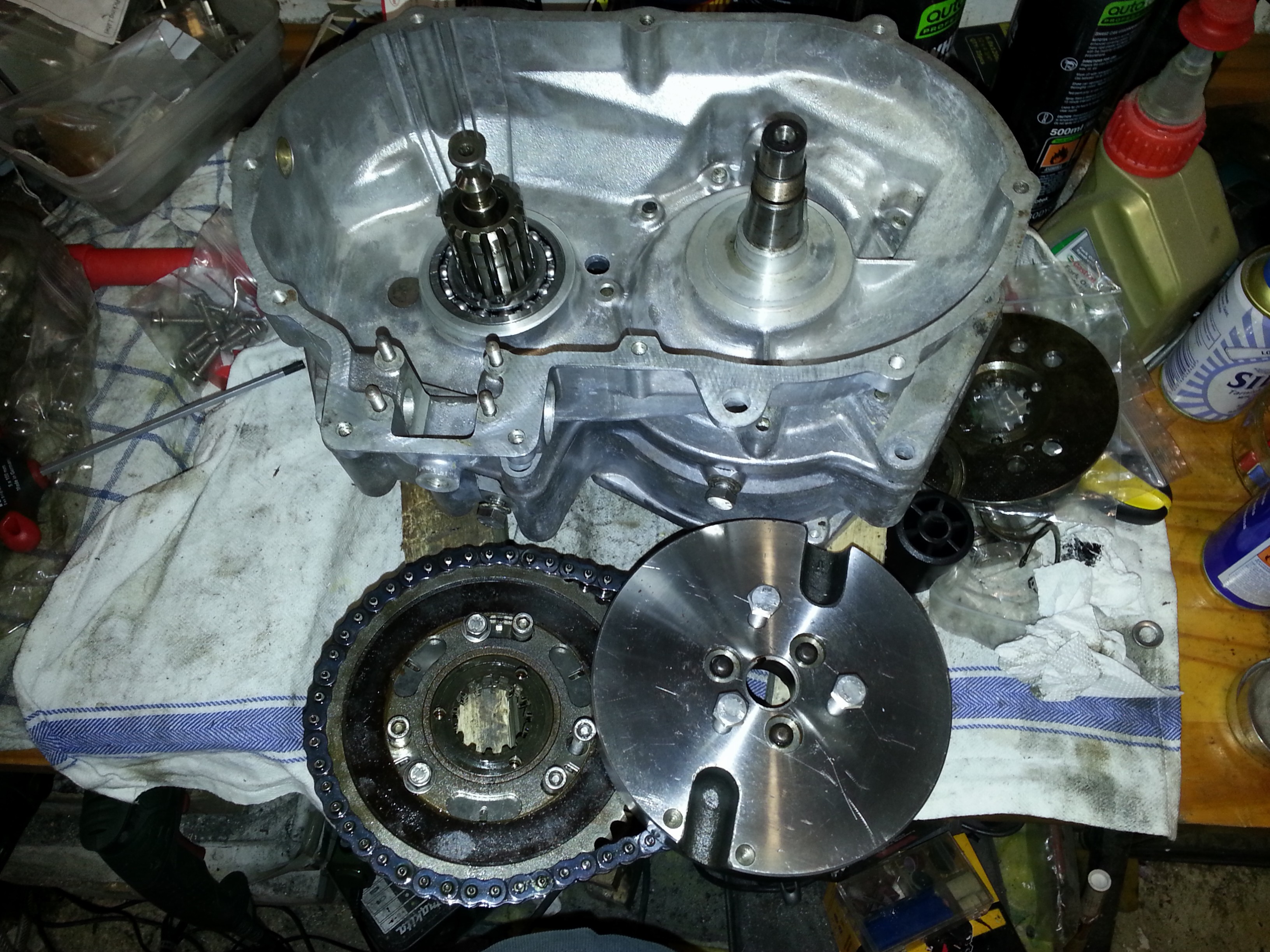
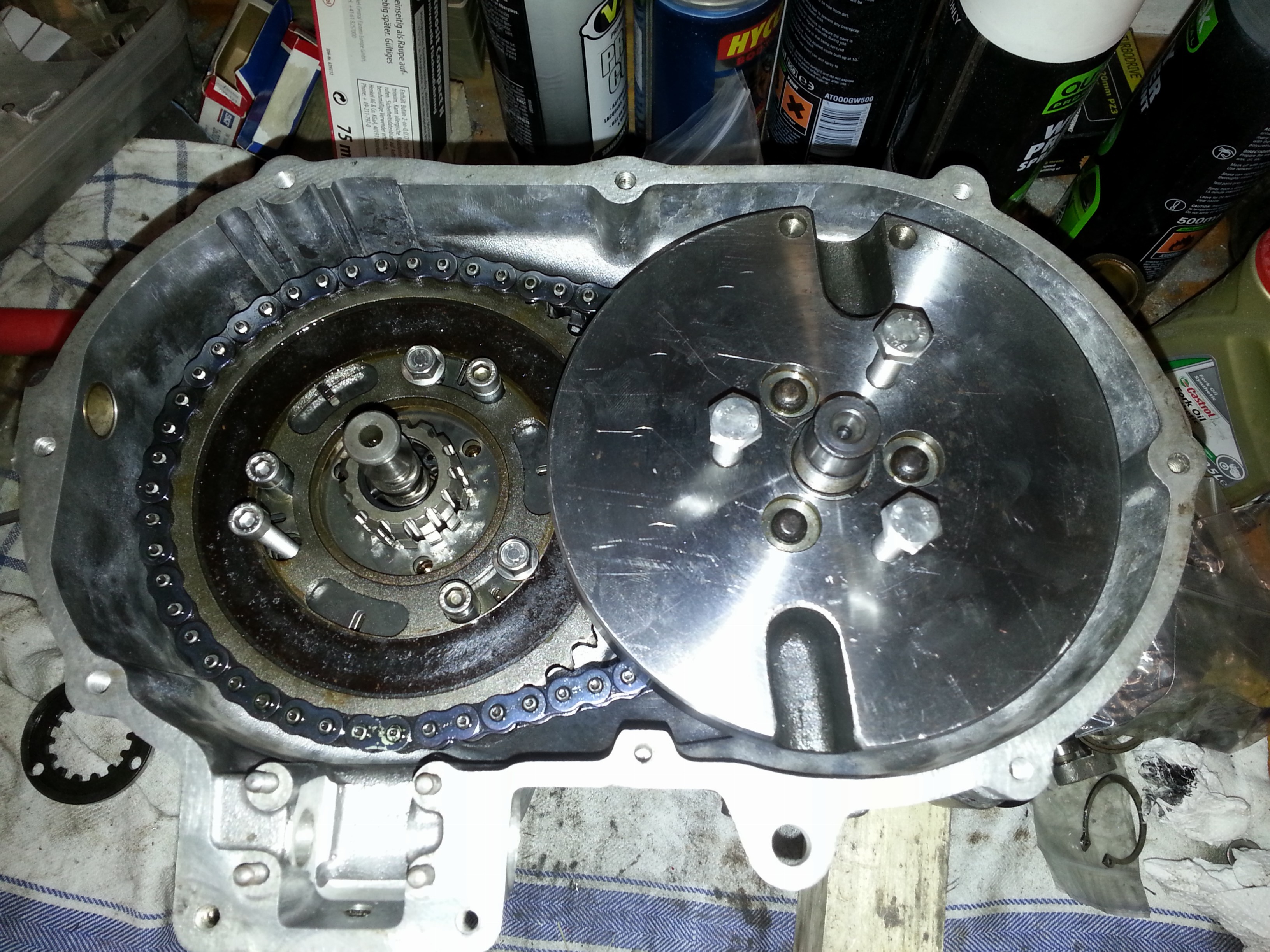
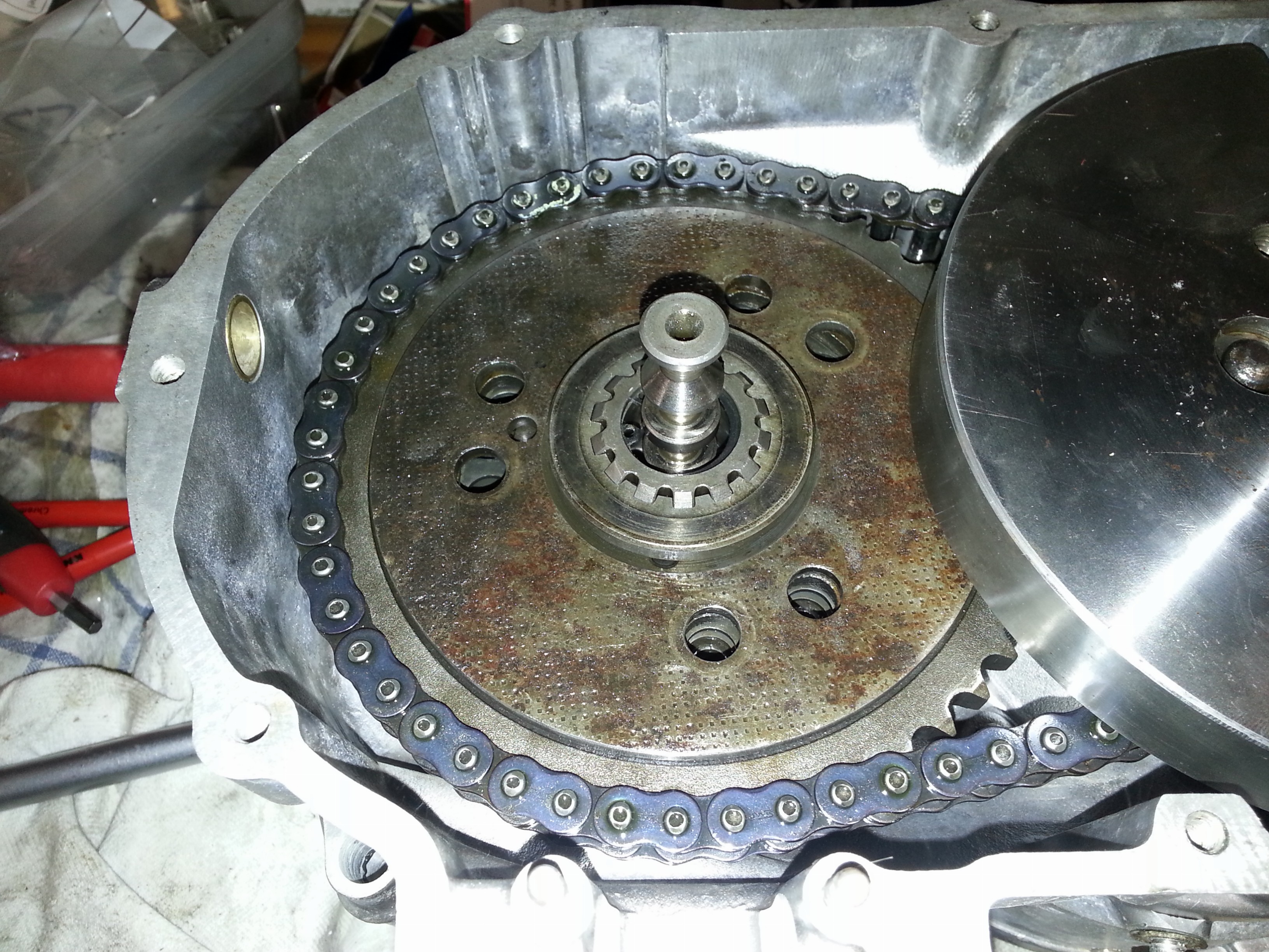
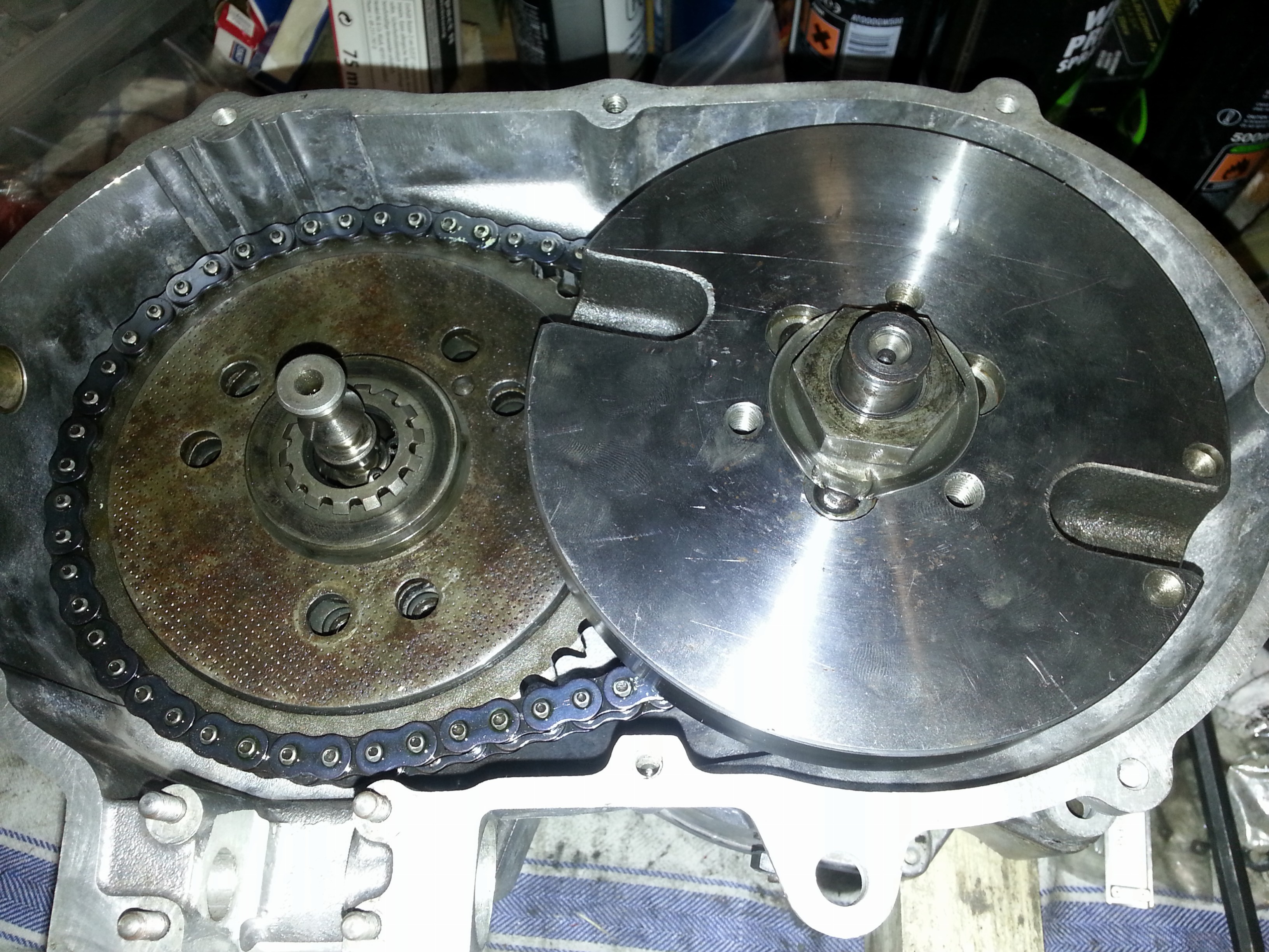
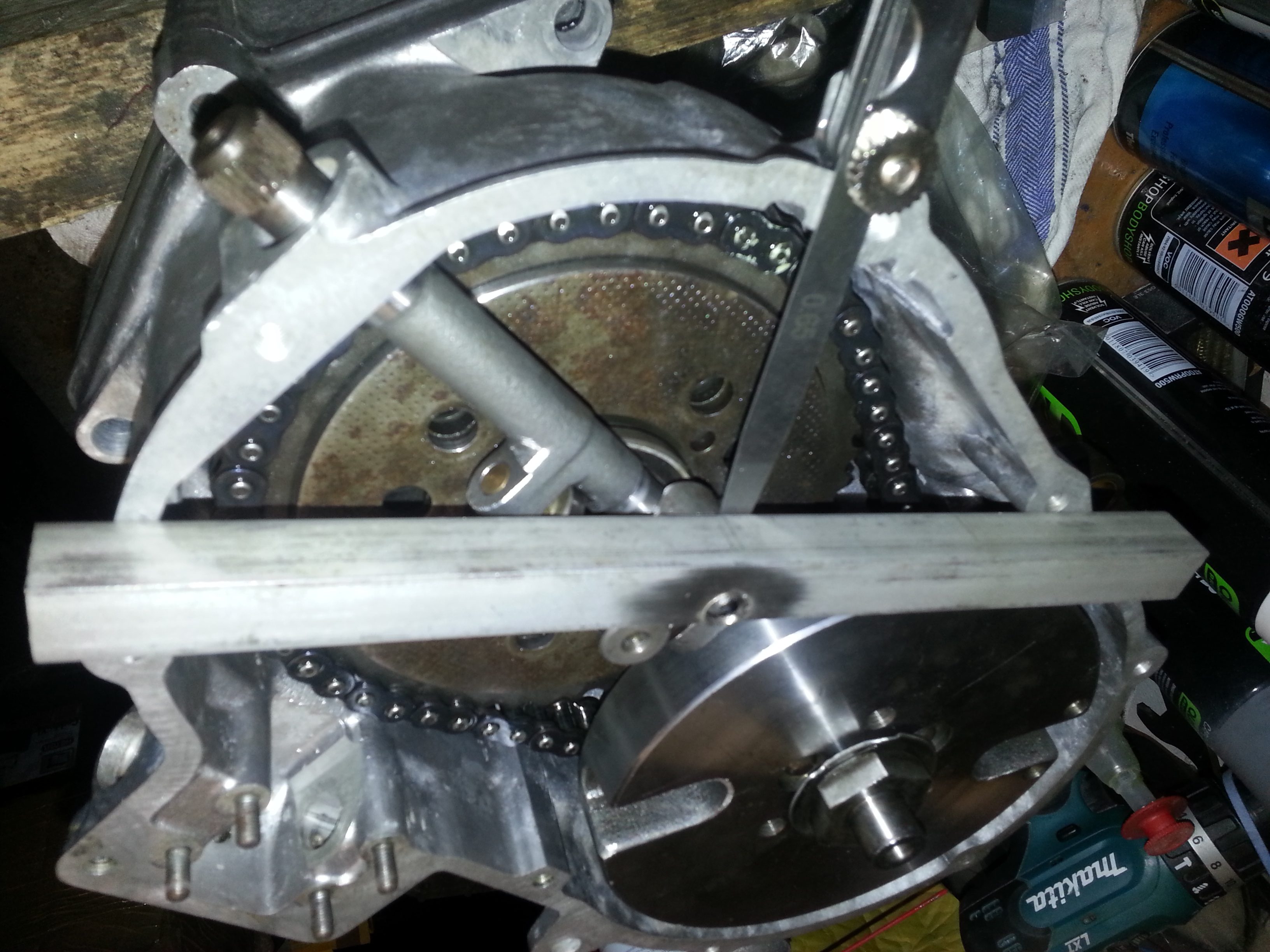
A peculiarity of the 200 cc engine series is that you can only take the clutch stack out together with the flywheel and vice versa. So next we’ll take the clutch stack, put the chain on that connects it with the flywheel and insert the flywheel. We’ll put a few bolts in the flywheel as well as it’s quite heavy. As a set it looks like this:
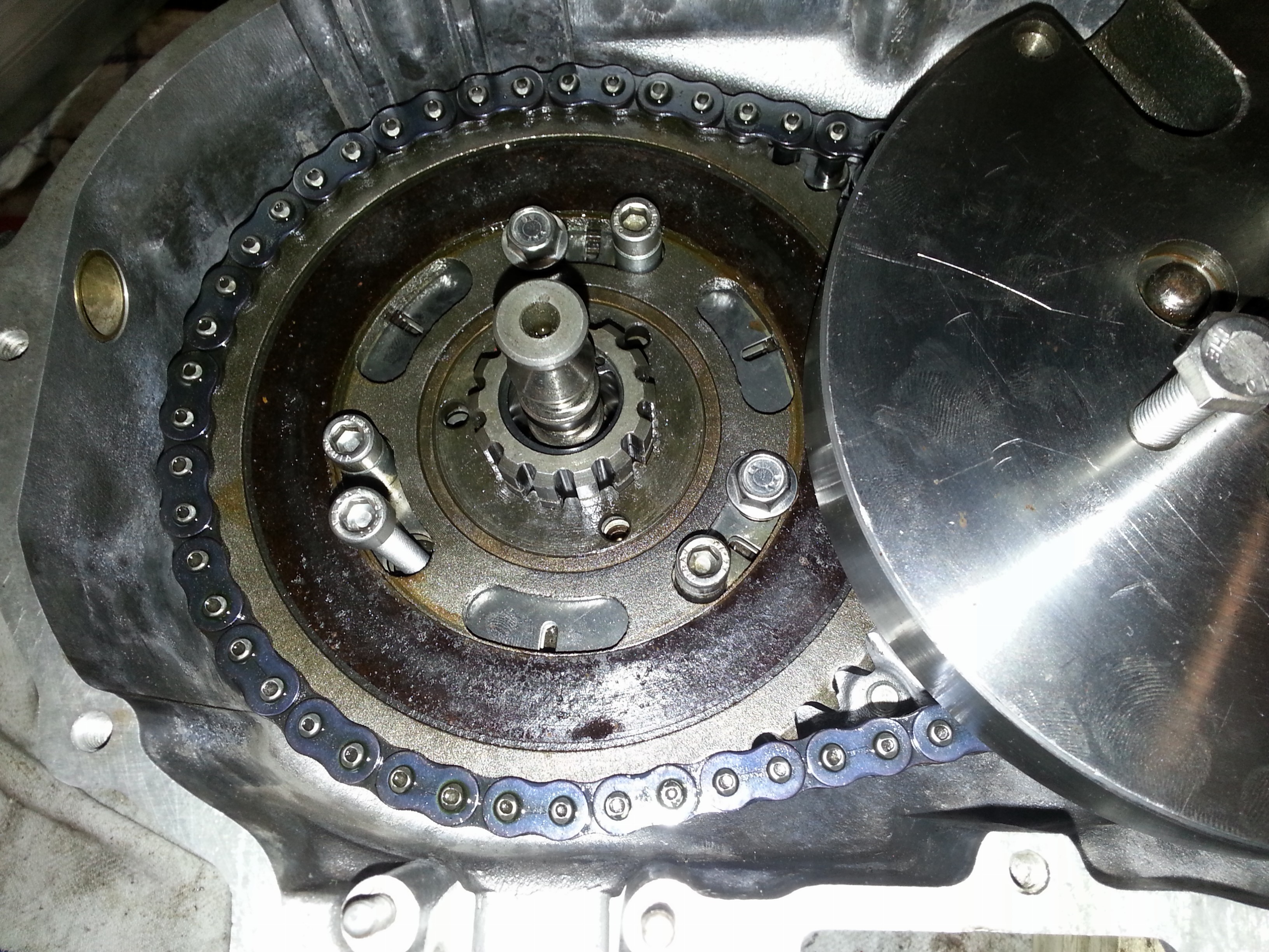
Now the trick is to slide the clutch stack and the flywheel in one go over both the crankshaft and the gear shaft. Before we do though, let’s put the woodruff key in the crankshaft:
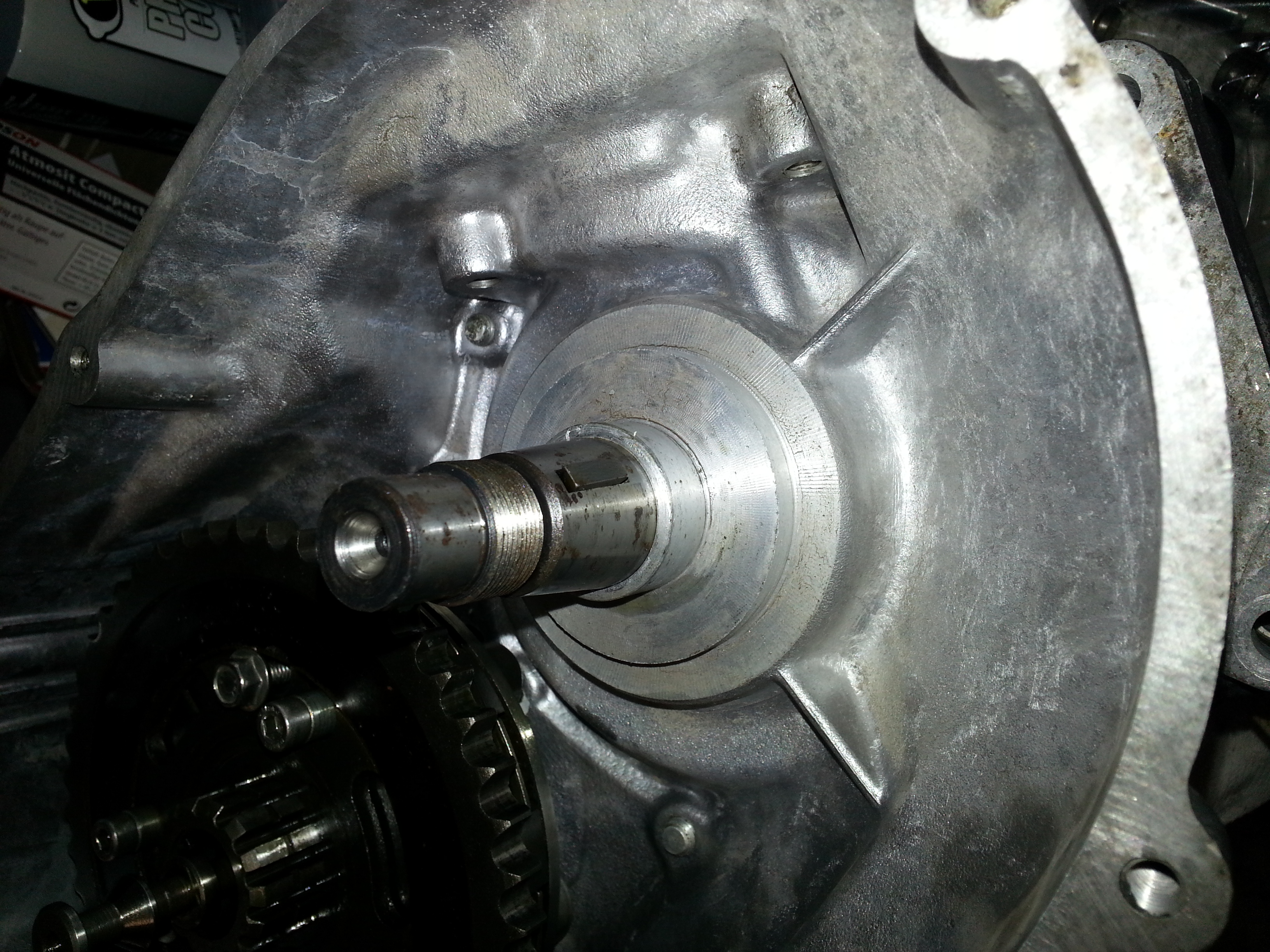
Next we put both stacks in. It’s a bit tricky, so gently gently does the job:
Time to secure our work with a Seeger ring:
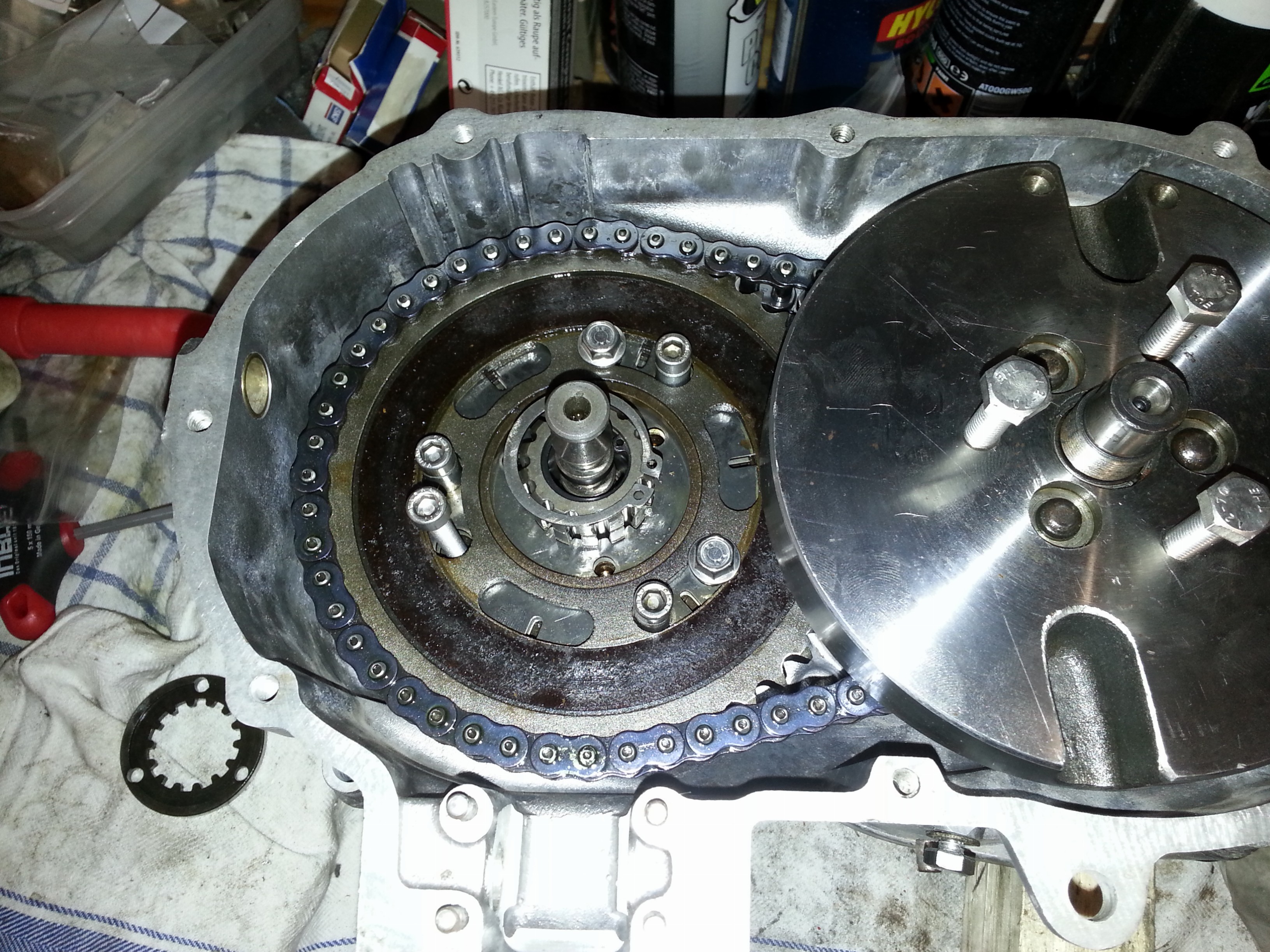
With a little wriggling the ring will snap into place:
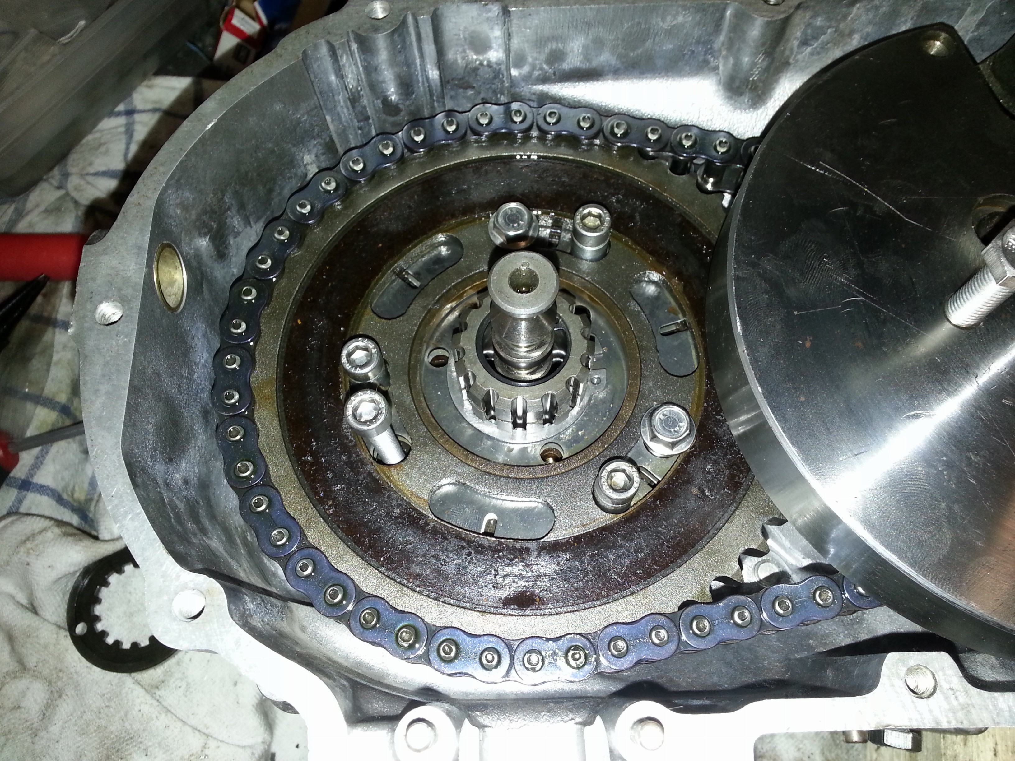
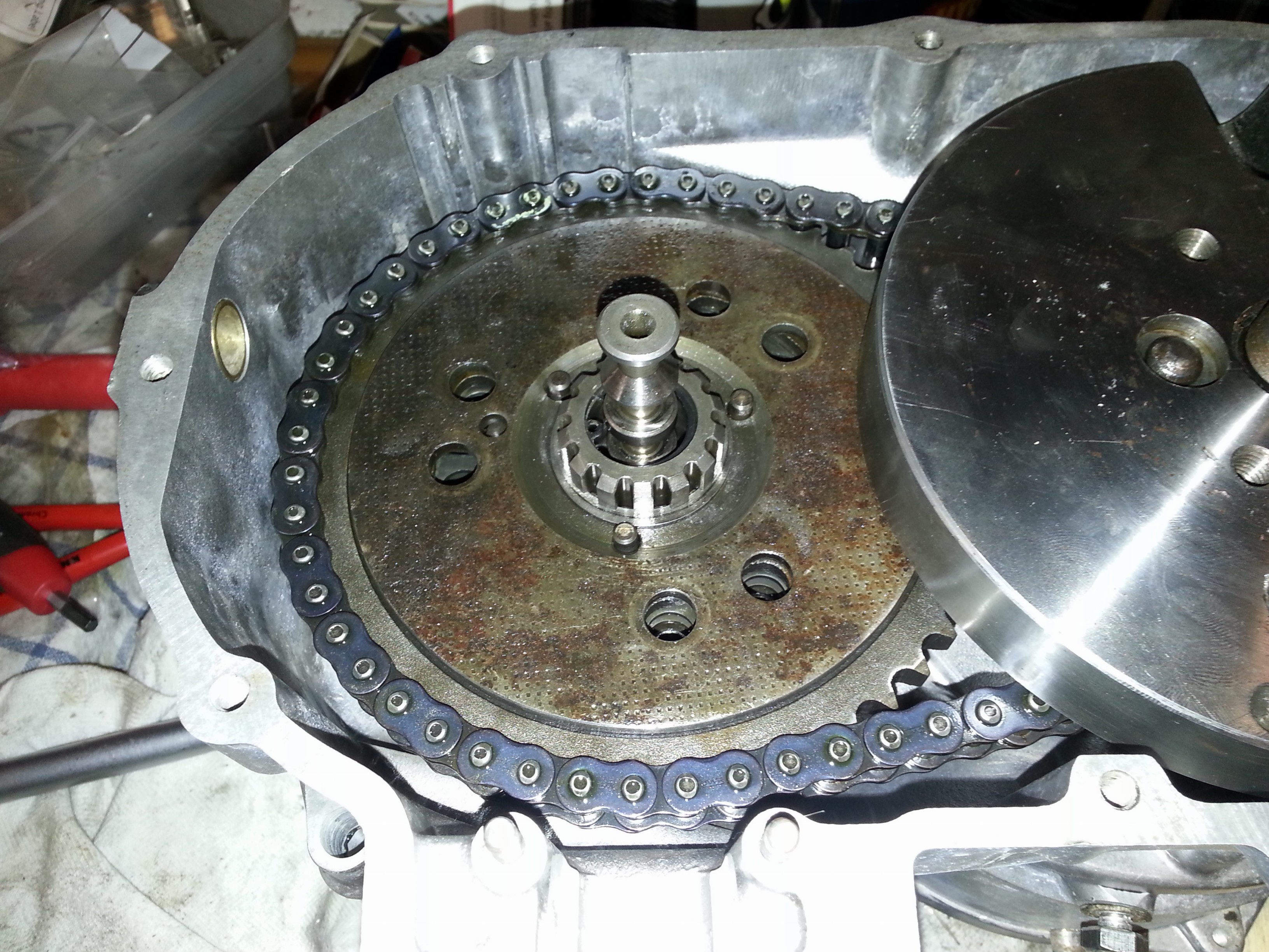
We’ve now secured the clutch stack into place. However, the gear wheel is not centered at this time. We need to insert the center plate which will cover the Seeger ring. Keep in mind that you will need to keep the holes for the clutch pins free and the center plate will only fit in one way:
 :
:
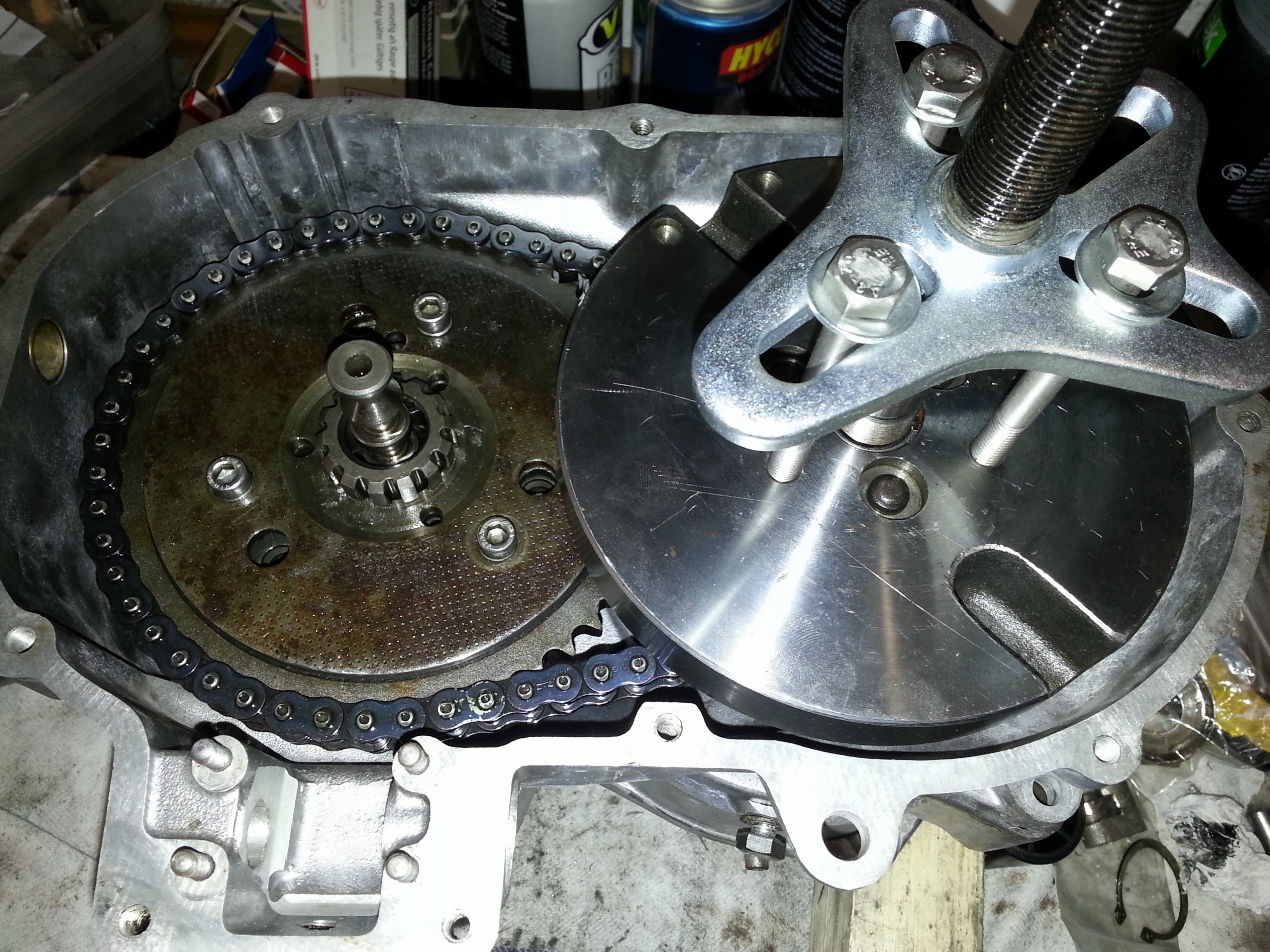
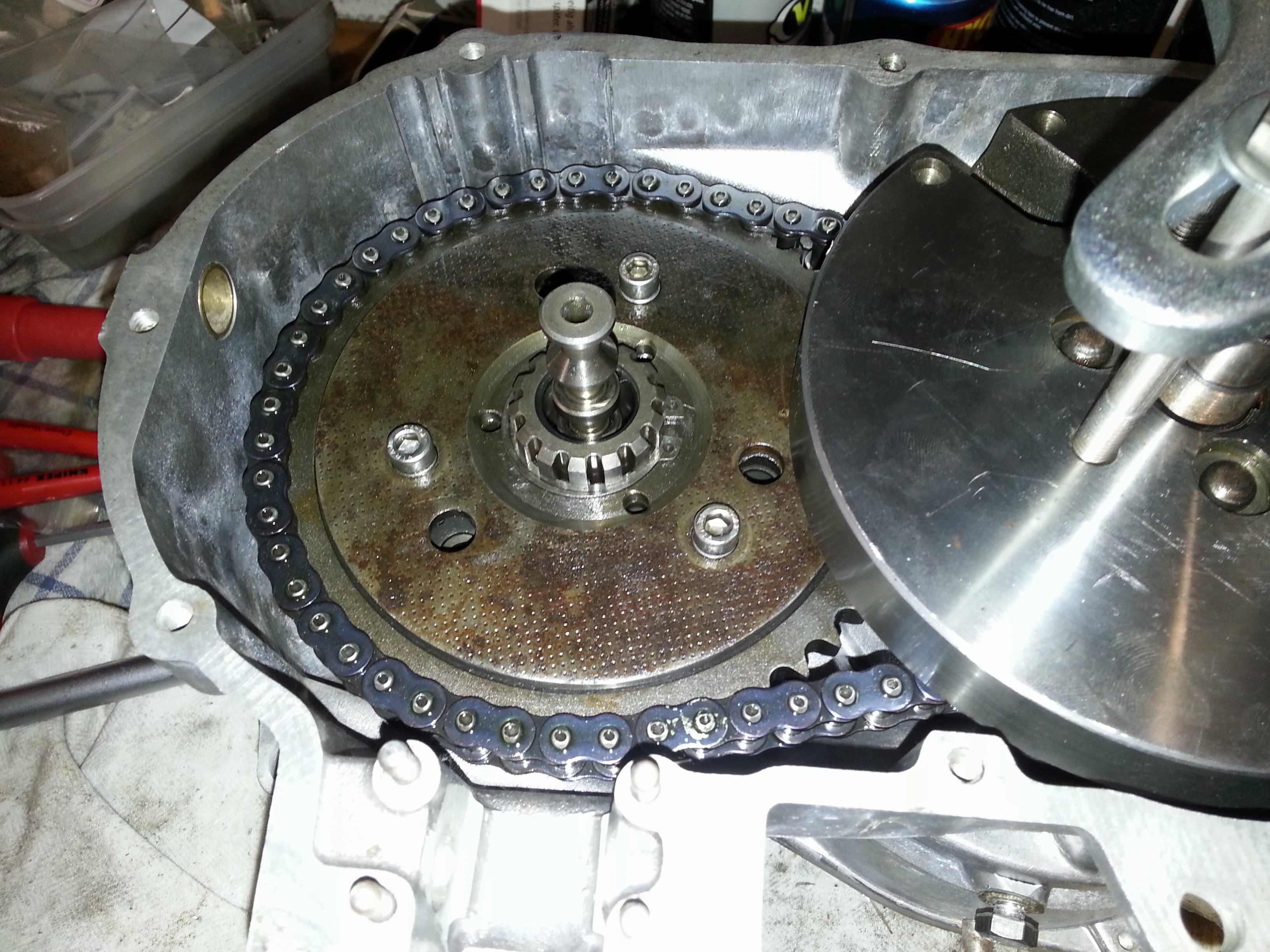
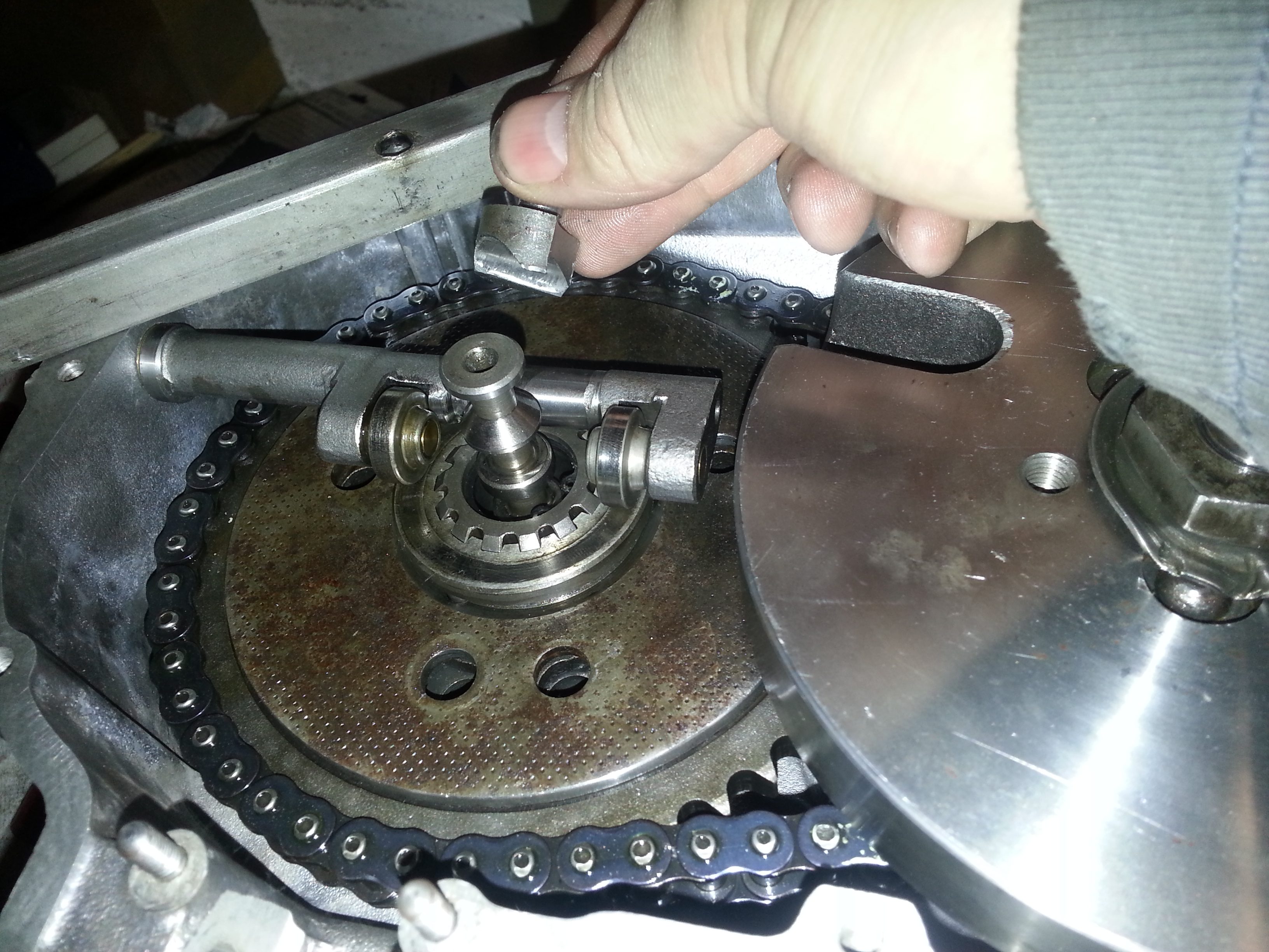
Now here’s a lessen; don’t push the flywheel on too tight as it will need to be lifted a little to put on the clutch cover plate. I had to use a puller to do so; keep in mind again, leave the clutch pin holes free:
Next we’ll put the second Seeger ring in place:
Now the clutch stack is ‘stable’ and we can remove the holding screws. It’s important that the clutch stack ‘settles’ a bit so take a rubber hammer and tap around the stack.
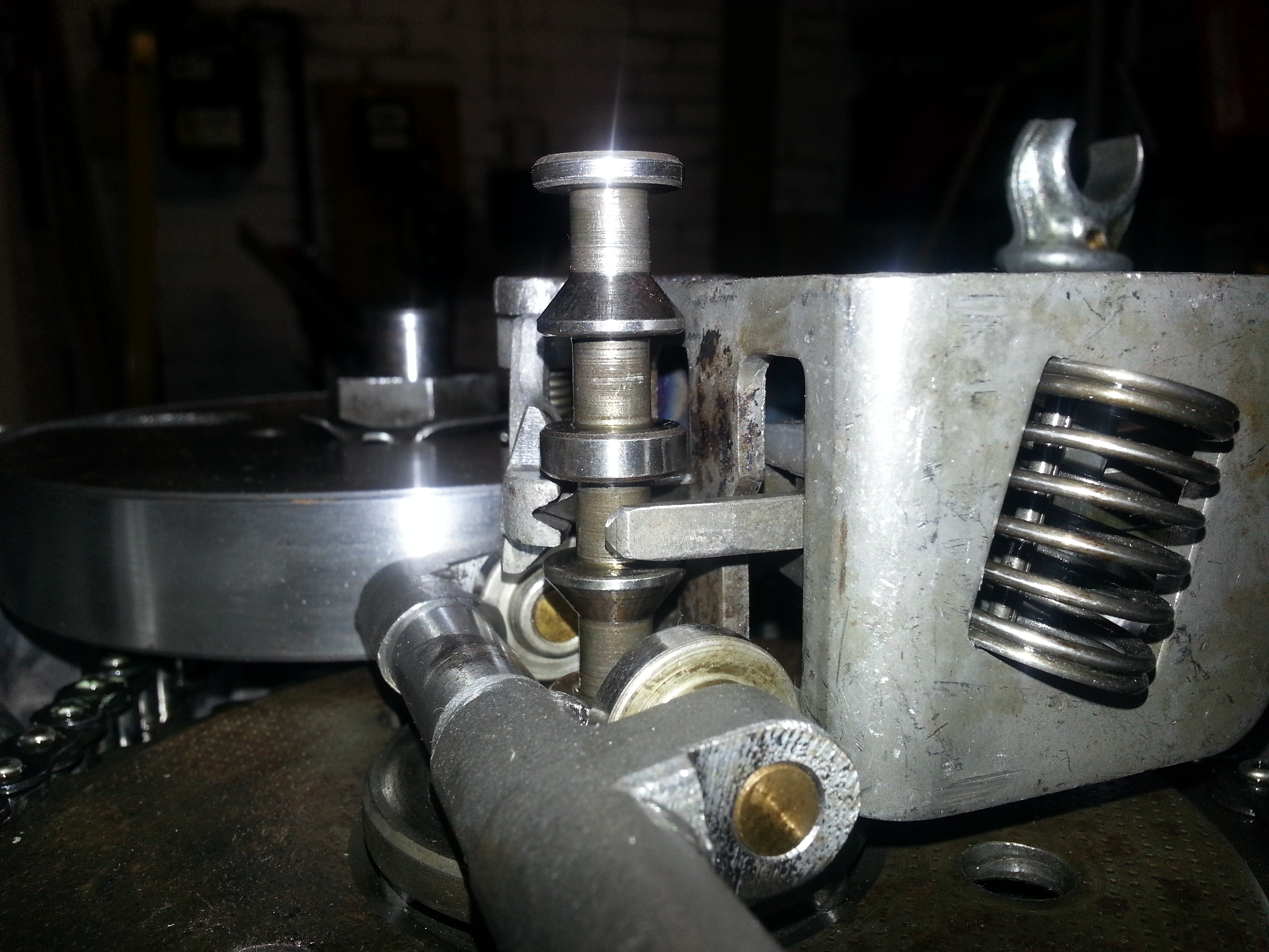
Next we need to insert the clutch pins. This is a tricky procedure as the clutch will rattle if the pins are not in the right holes. If marked when taking them out, it’s easy. If not (like me) you will need to measure the distance from the top of a pin to a measuring bar set across the engine half. You may want to repeat the measurement three times to be sure. Once ready the pins in place will look like this (play is not to exceed 0.02 to 0.03 mm according to the workshop manual!):
A final clutch pressure ring is laid on top of the pins. You will have noticed that the pins stick out slightly from the clutch cover plate so the pressure ring, when depressed, will engage the clutch. This is done by the clutch pressure bar which we’ll install in a minute. You can imagine that if the pins are not of the right length there will be a wobble when depressing the pressure ring. The pressure ring in place looks like this:
Now we’re almost done with the clutch stack and the flywheel. What remains is to secure the flywheel by putting the flywheel securing ring on and the nut. Once the nut is tightened, the securing ring can be hammered back into place:
Not that the securing ring gets hammered down into a depression on one side and against the nut on the opposite so the nut can’t go anywhere.
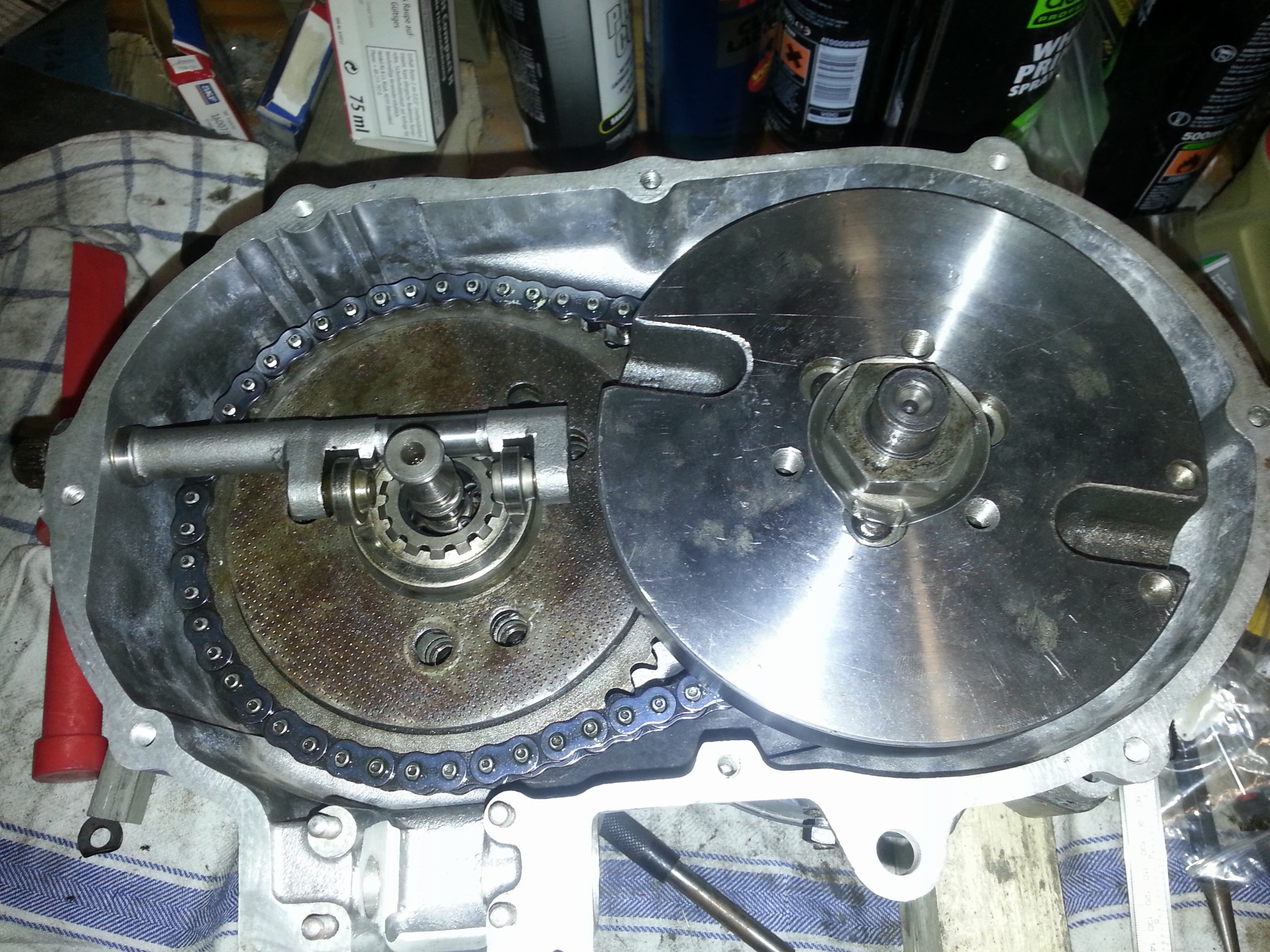
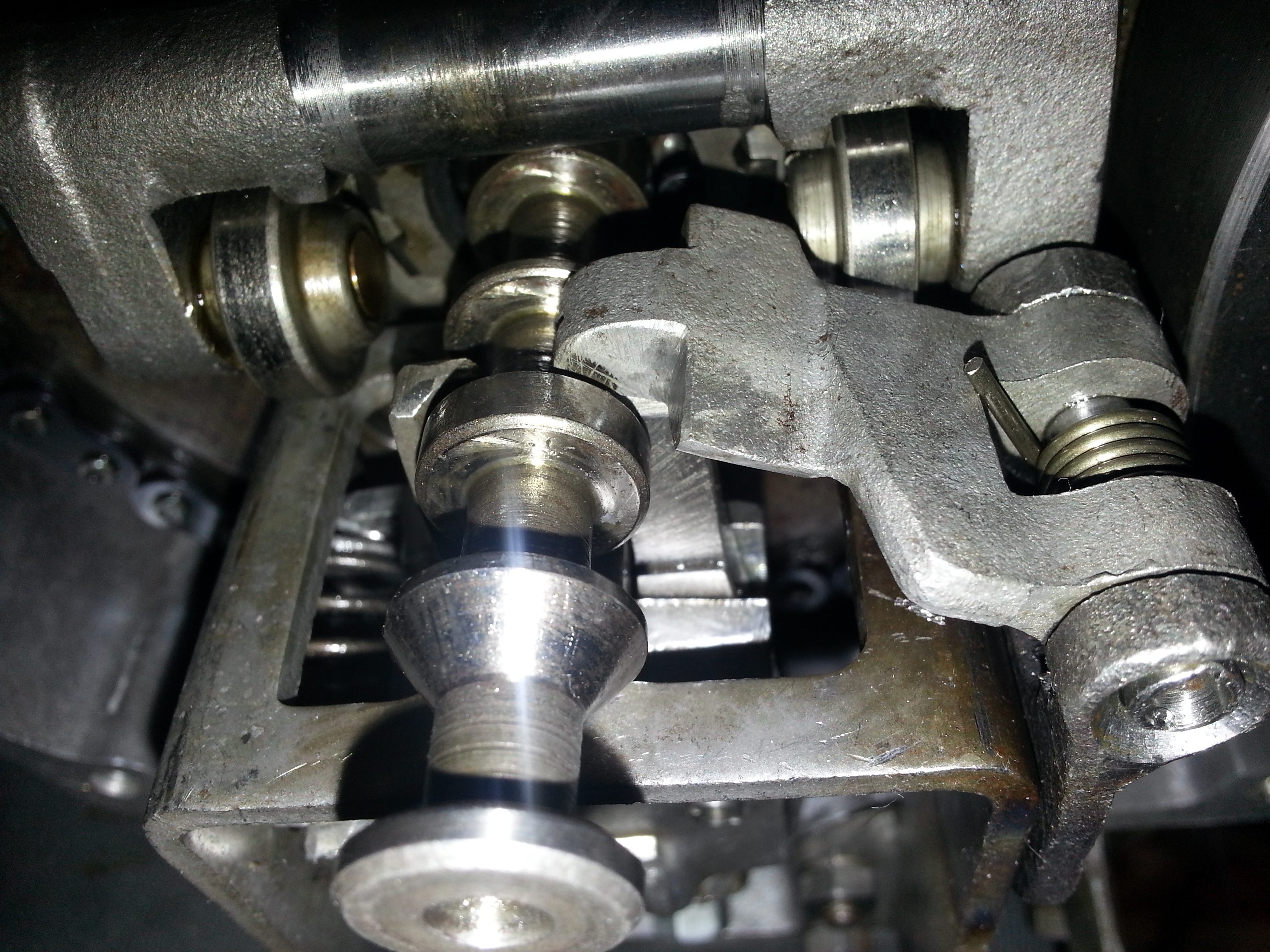
Next we’ll install the clutch pressure bar:
Once installed, you need to see whether the support pin of the clutch bar is close enough to the bar to keep it in place. To do so, take a metal bar with an 8mm hole and put the pin inside:
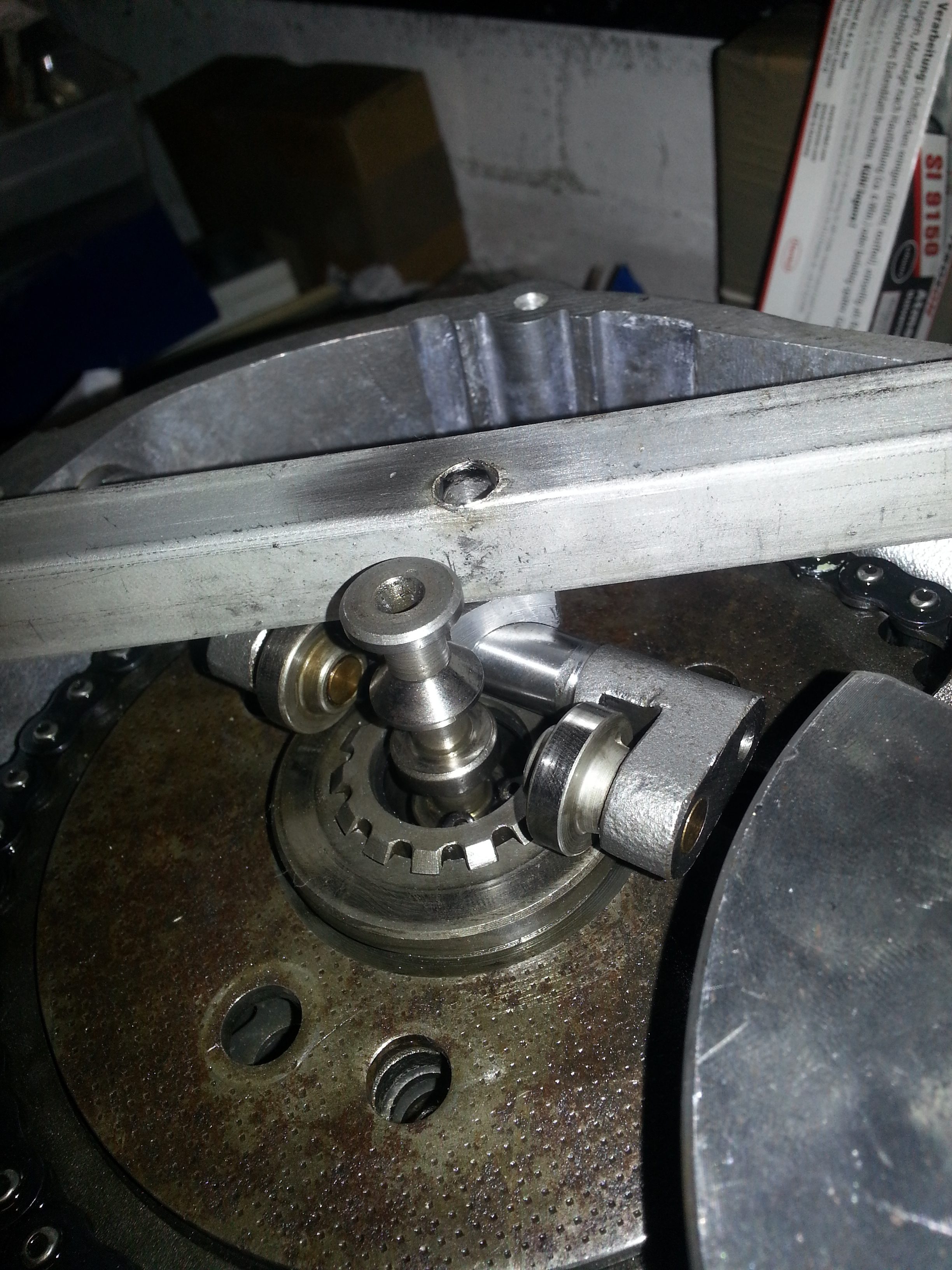
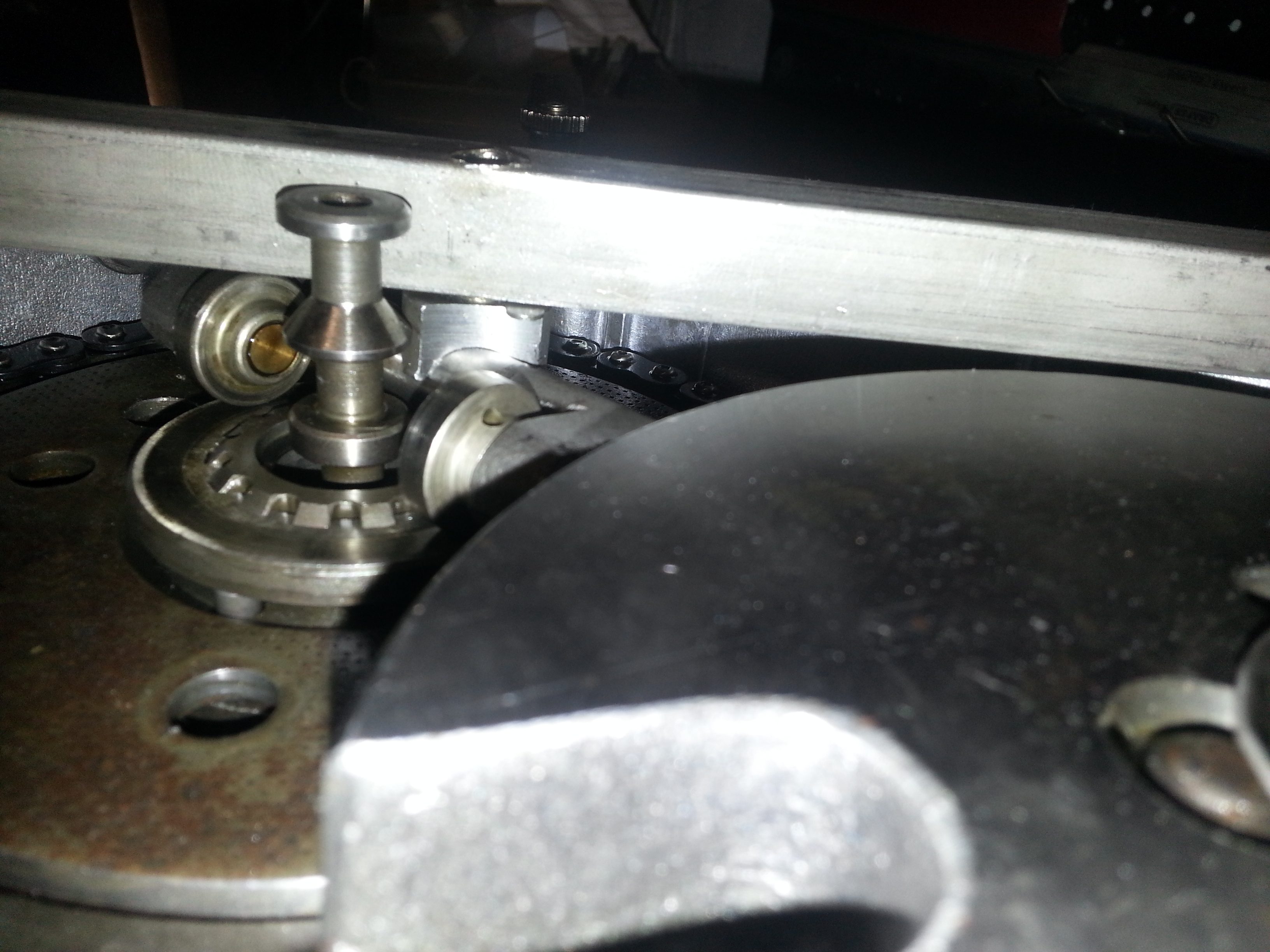
You can now see the play that the pin has. Use a feeler gauge to measure the gap:
Play should be minimal (e.g. 0.1 mm) and standard shims with M8 holes can be used to take up the slack. Do make sure that the clutch pressure bar is level and presses on the clutch pressure ring equally on both sides. You can fit the clutch cover before installing the clutch cover bearing to test the play of the clutch pressure bar.
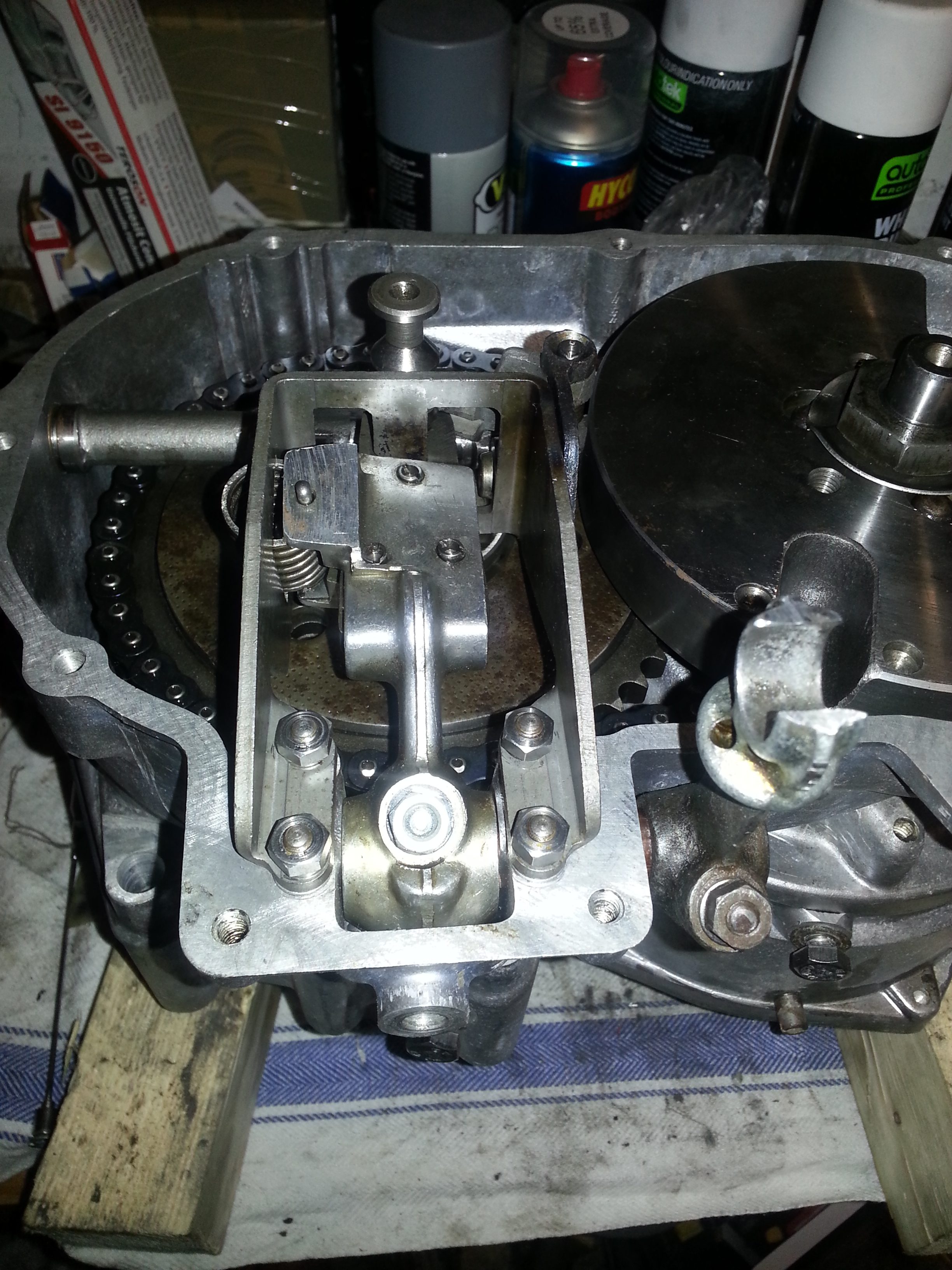
Next we install the gear selector fork. It’s is key to put the shims back right that held it in place. These are under the two sets of screws holding the fork to the engine half:
The idea of the shims is that:
- The distance between two gear changes on the shaft protrusions is exactly equidistant
- This in turn allows the fork clamp to faill in place which prevents slipping out of gear (unless your gears are too worn
As you can see on the photo the selector is seated nicely beween the two protrusions (3rd gear position) and in the next photo how the gear clamp falls into place:
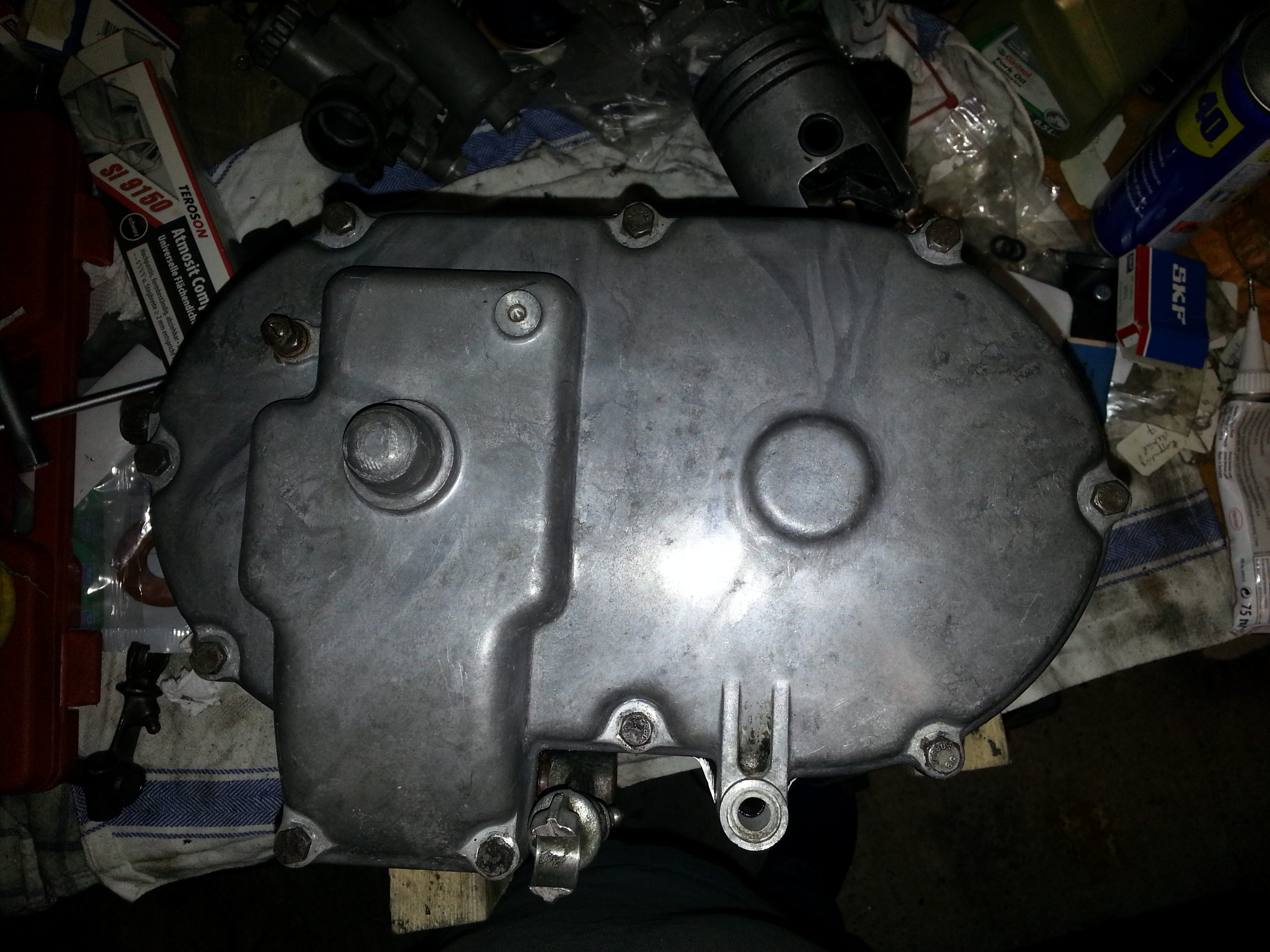
That completes the clutch side of the engine all that is left is to install a new bearing in the clutch cover and to make sure that the neutral gear switch rubbers are not gone and touching the casing:
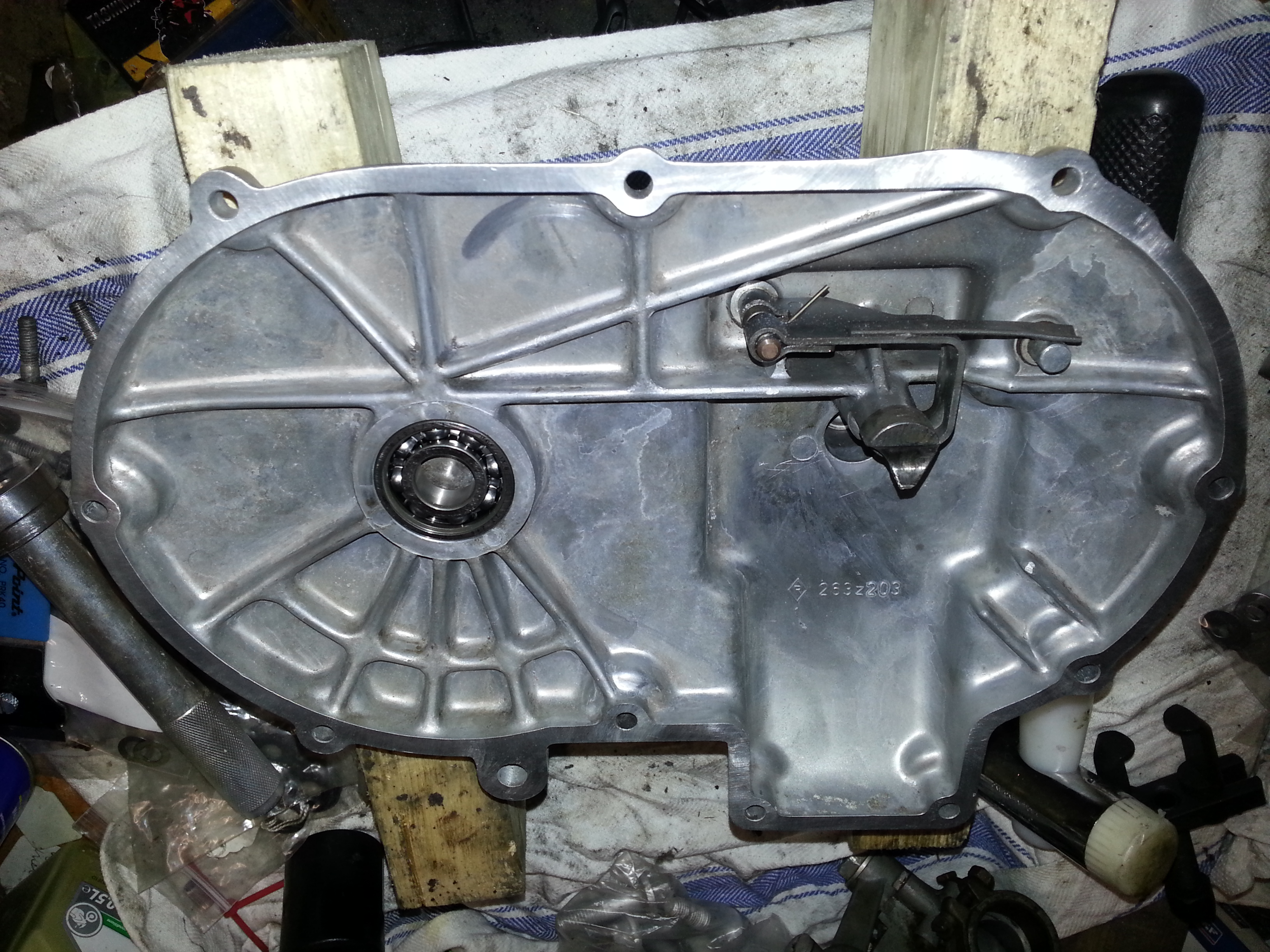
You can see the switch at the right top; it is the pin the metal piece is resting on. It makes contact with the pin when the gear is in neutral.
Then we install the cover (the bearing is a loose press fit and pushes onto the crankshaft easily.