The ignition switch in the Bella is one of a common type used for a number of scooters of the day. They are quite clever in design and relatively simplistic. The most common faults are:
- Wire soldered onto the switch have perished or multiple copper strands have broken off
- Cable ends were not soldered properly and as a result there is poor contact between the wire and connection point
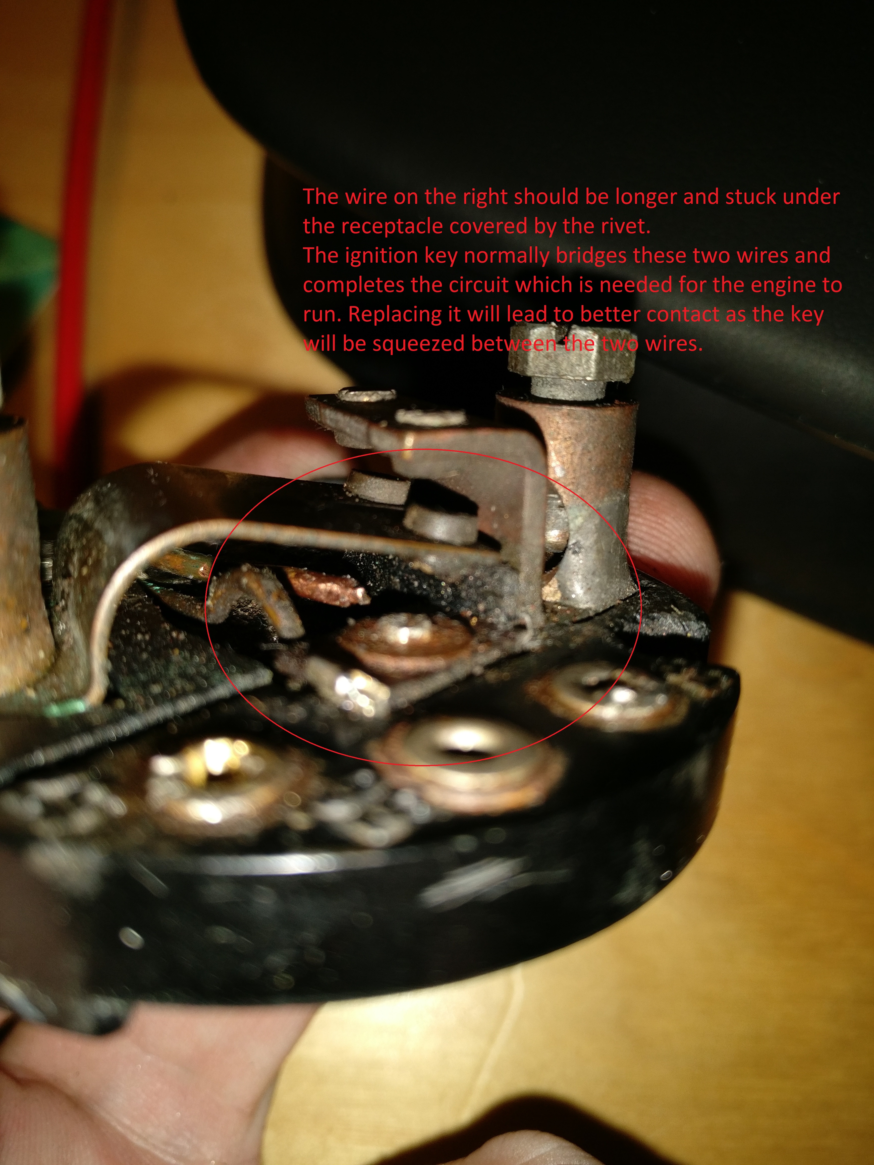
- There are two copper wires inside the switch between which the the ignition key rests. The key itself acts as a conductor for main power and ignition. These wires can break through metal fatigue over time as they get moved by the key time and again.
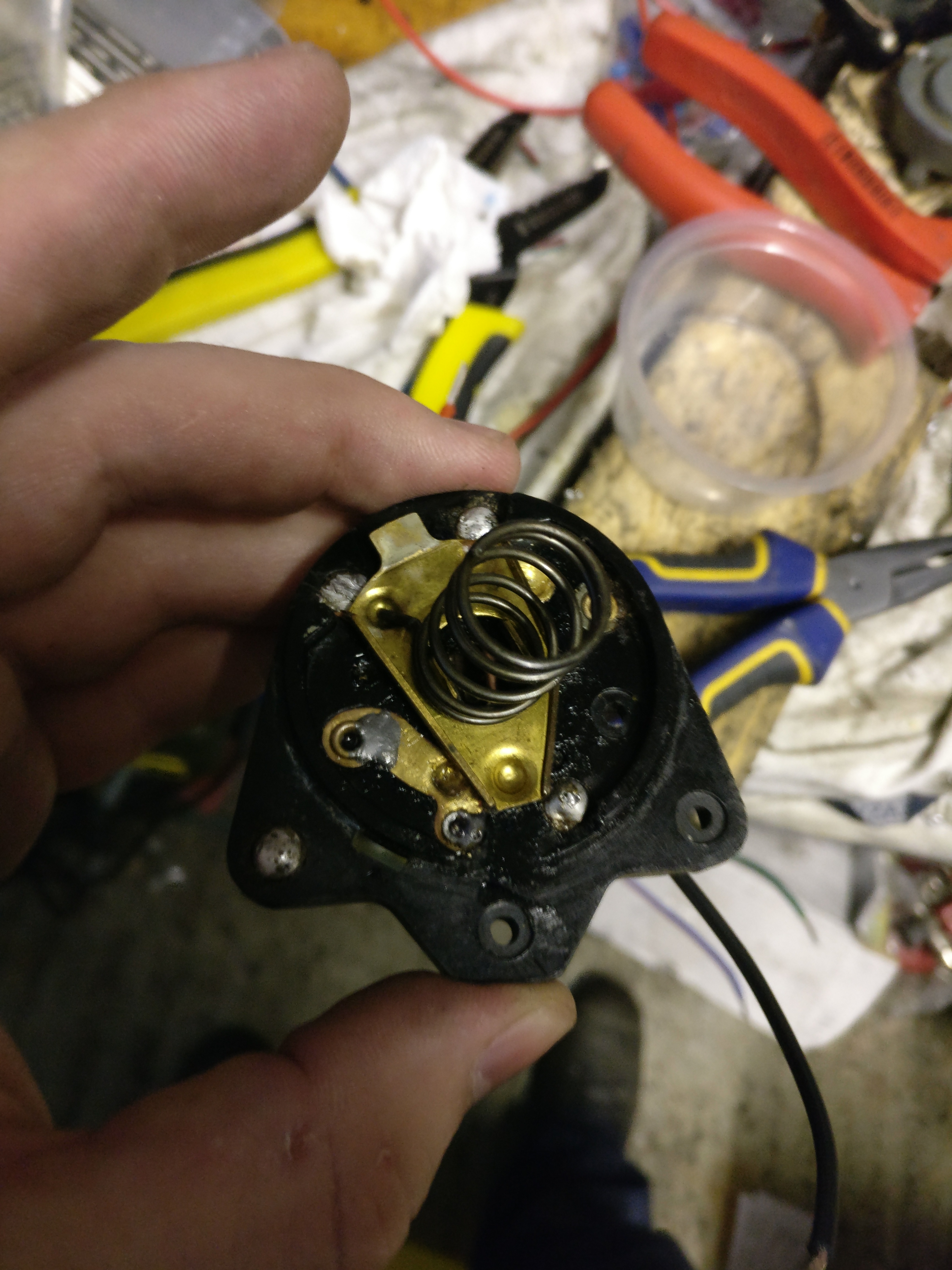
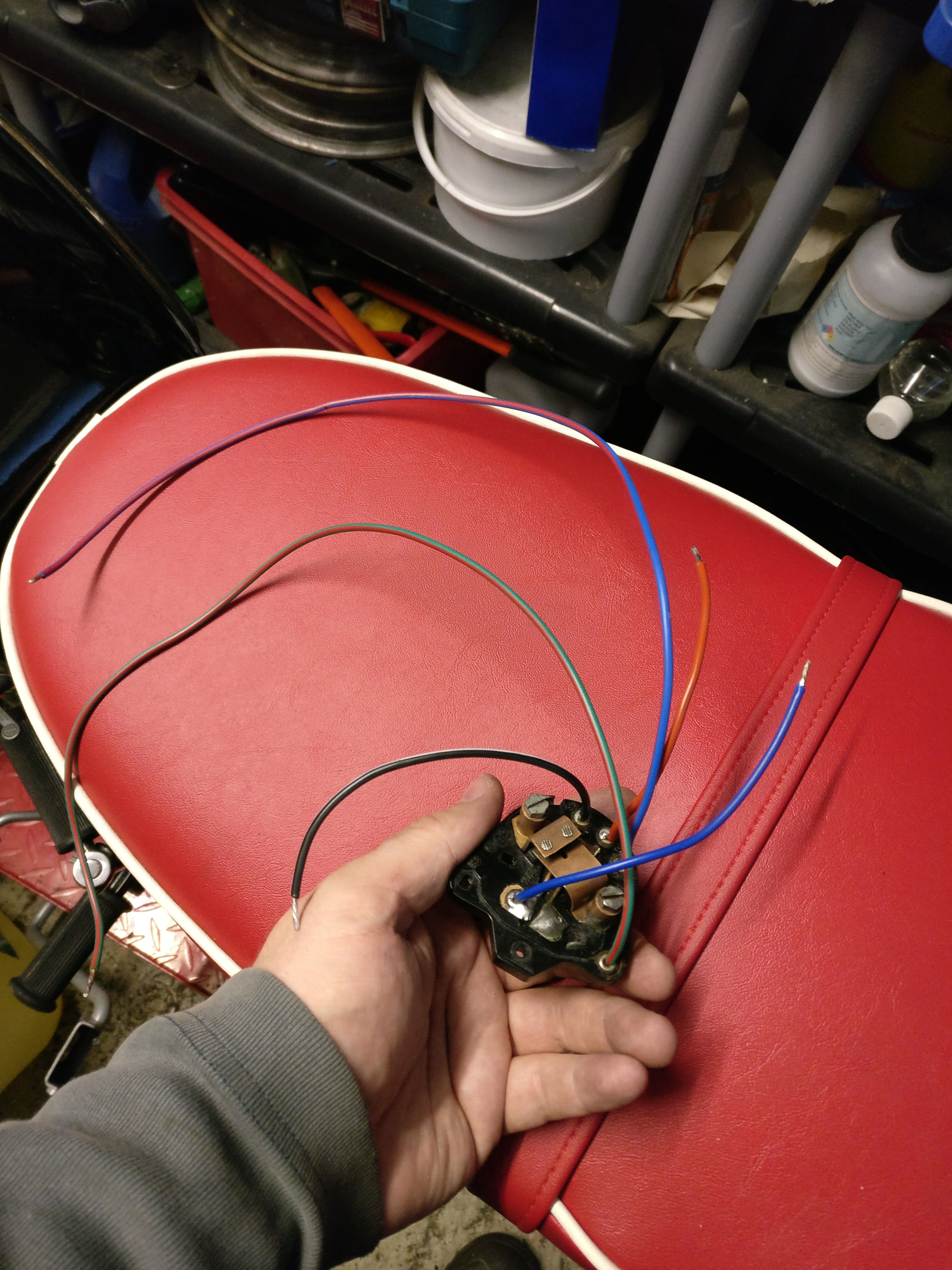
Let’s start with a NOS switch:
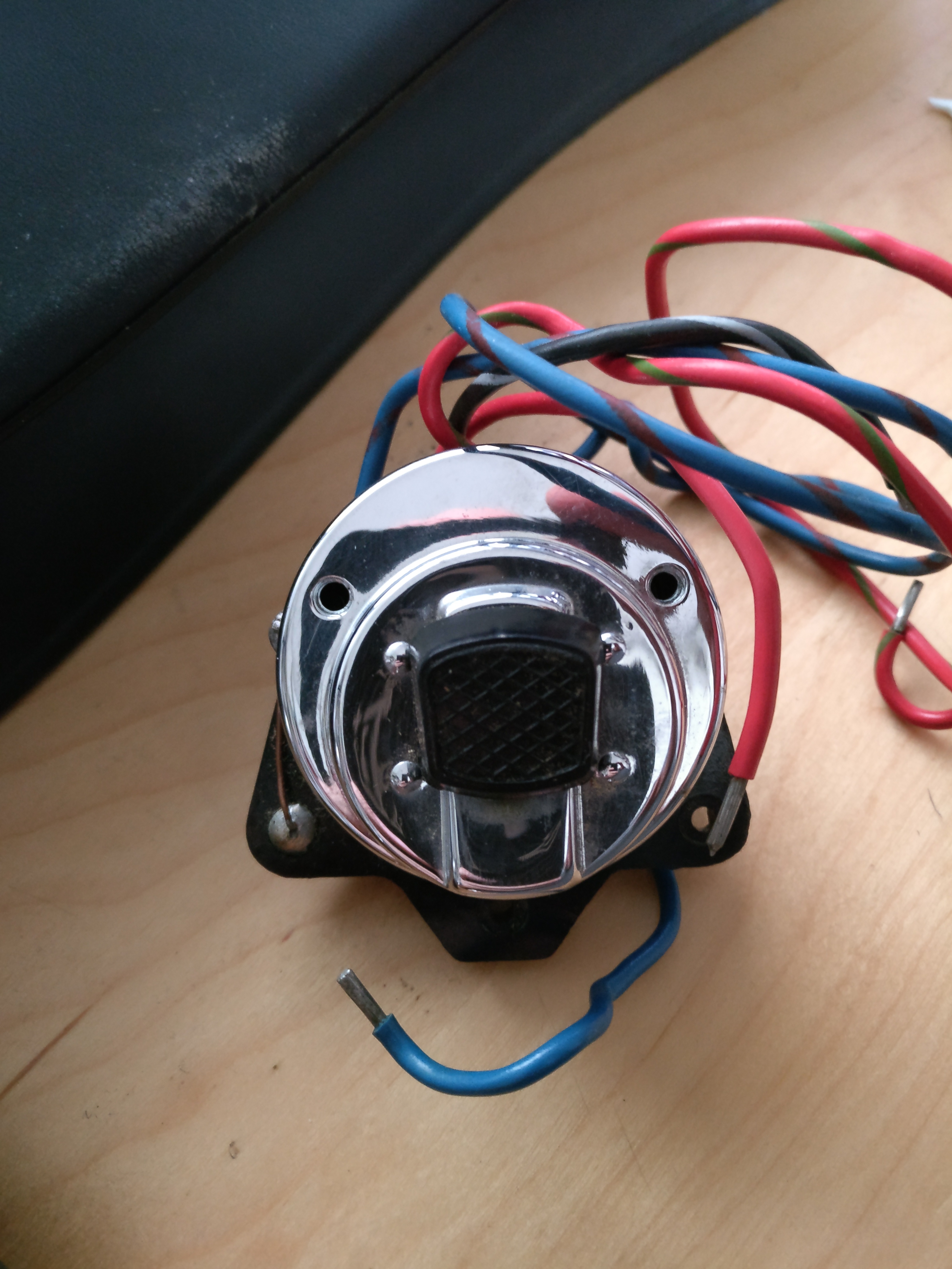
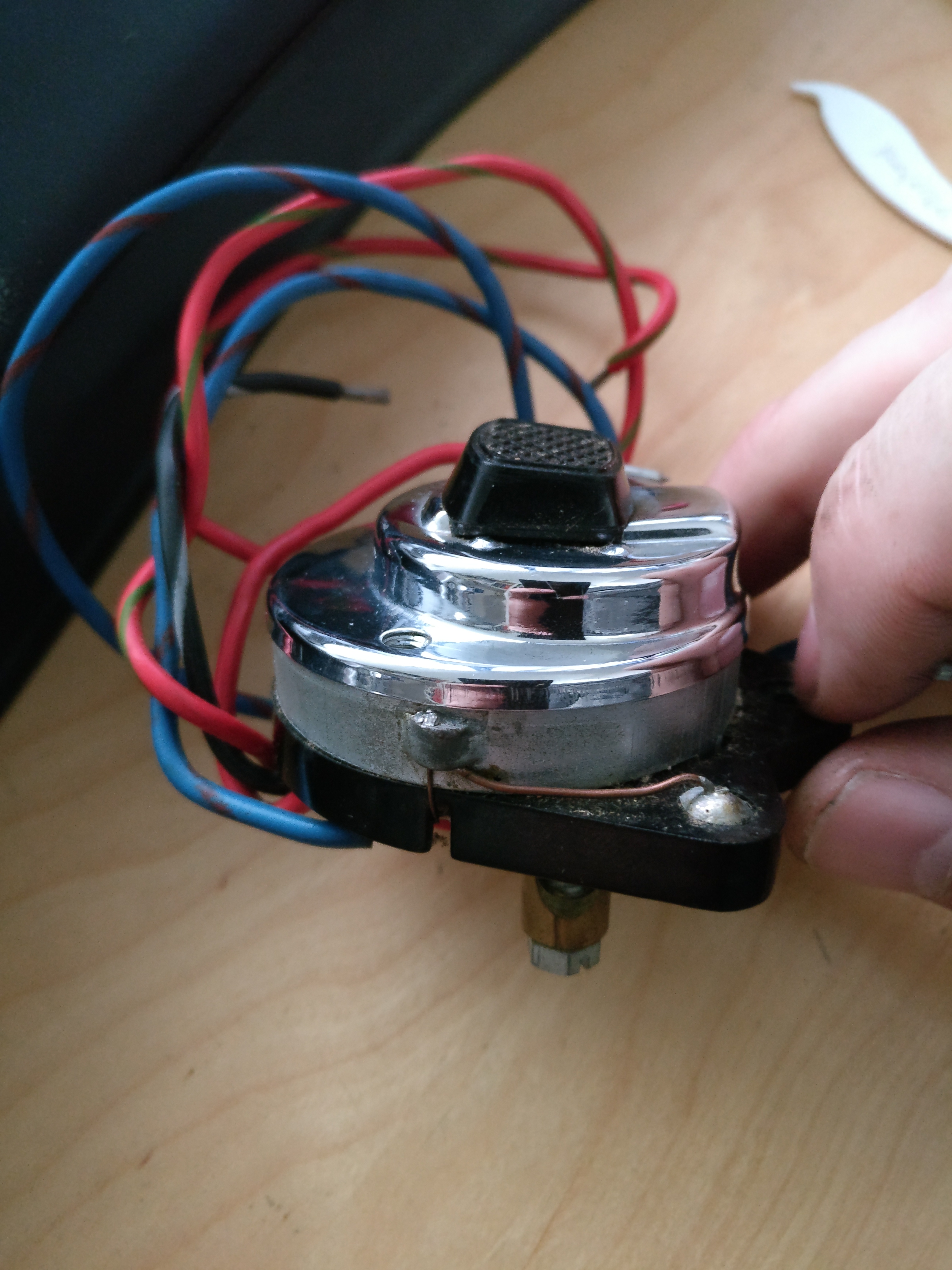
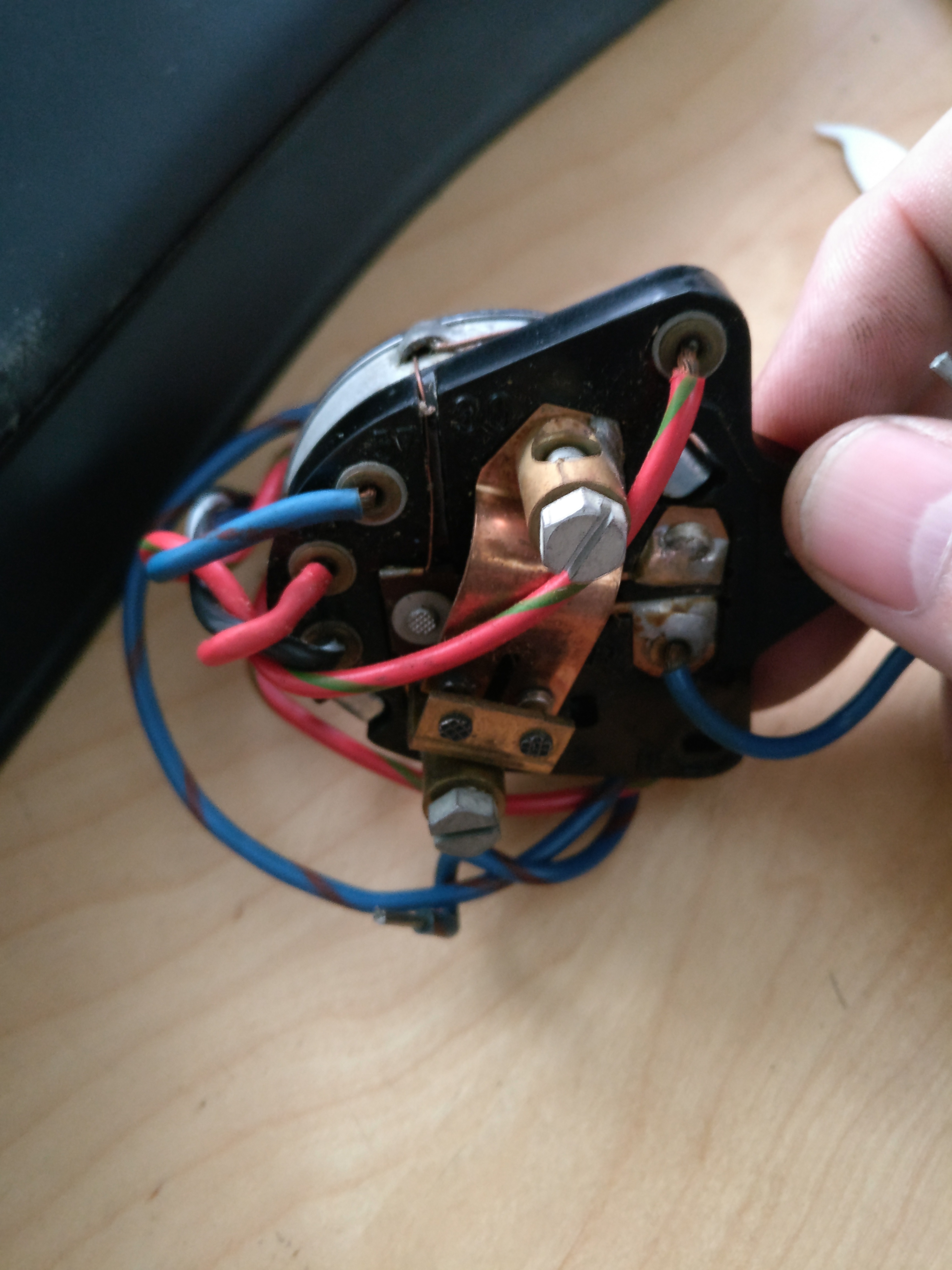
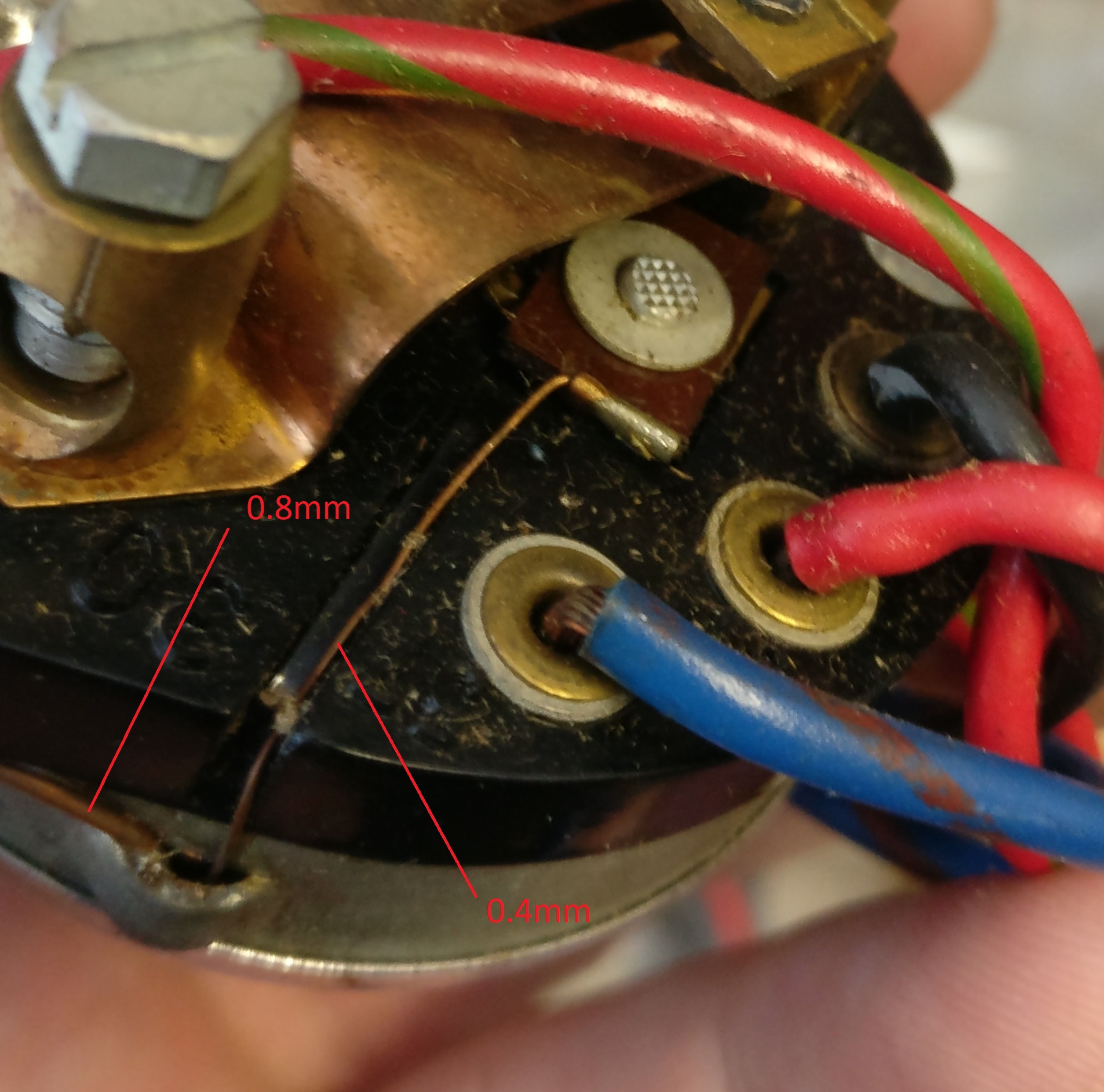
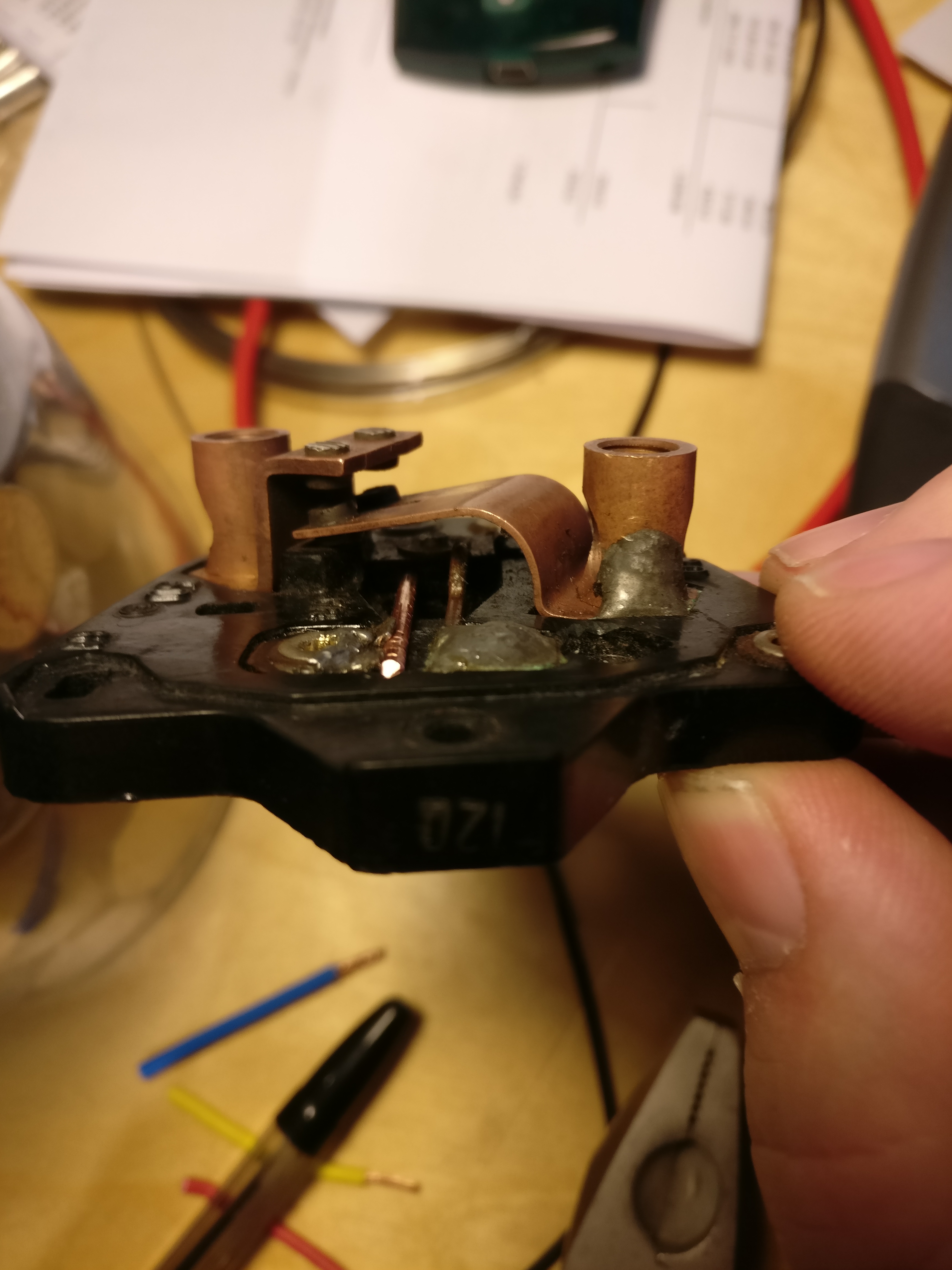
The two soldered wires are used to ground the switch; they are 0.8mm thick from casing to corner of switch and it is 0.4mm from the cover to the main contact – they act as fuses:
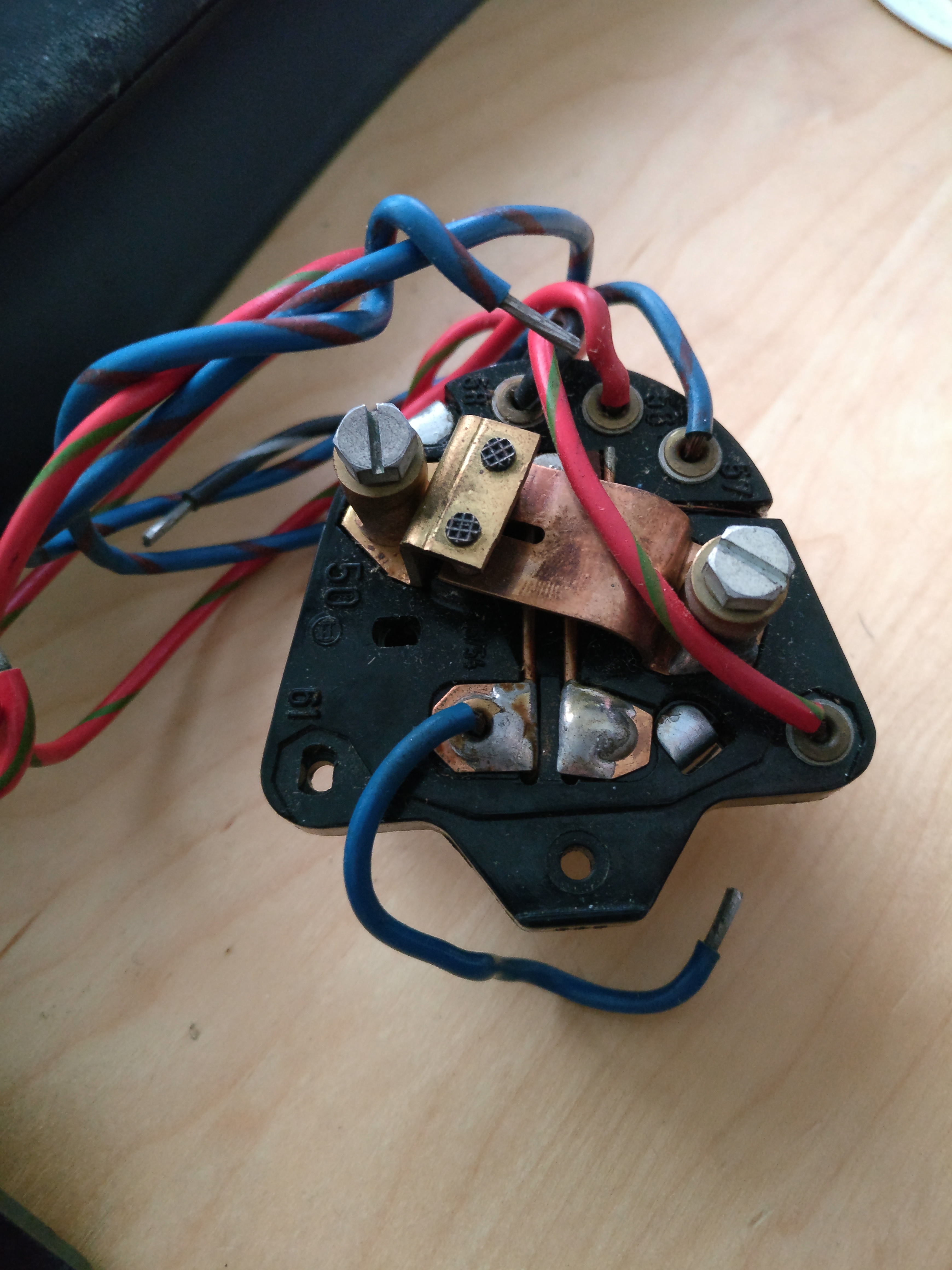
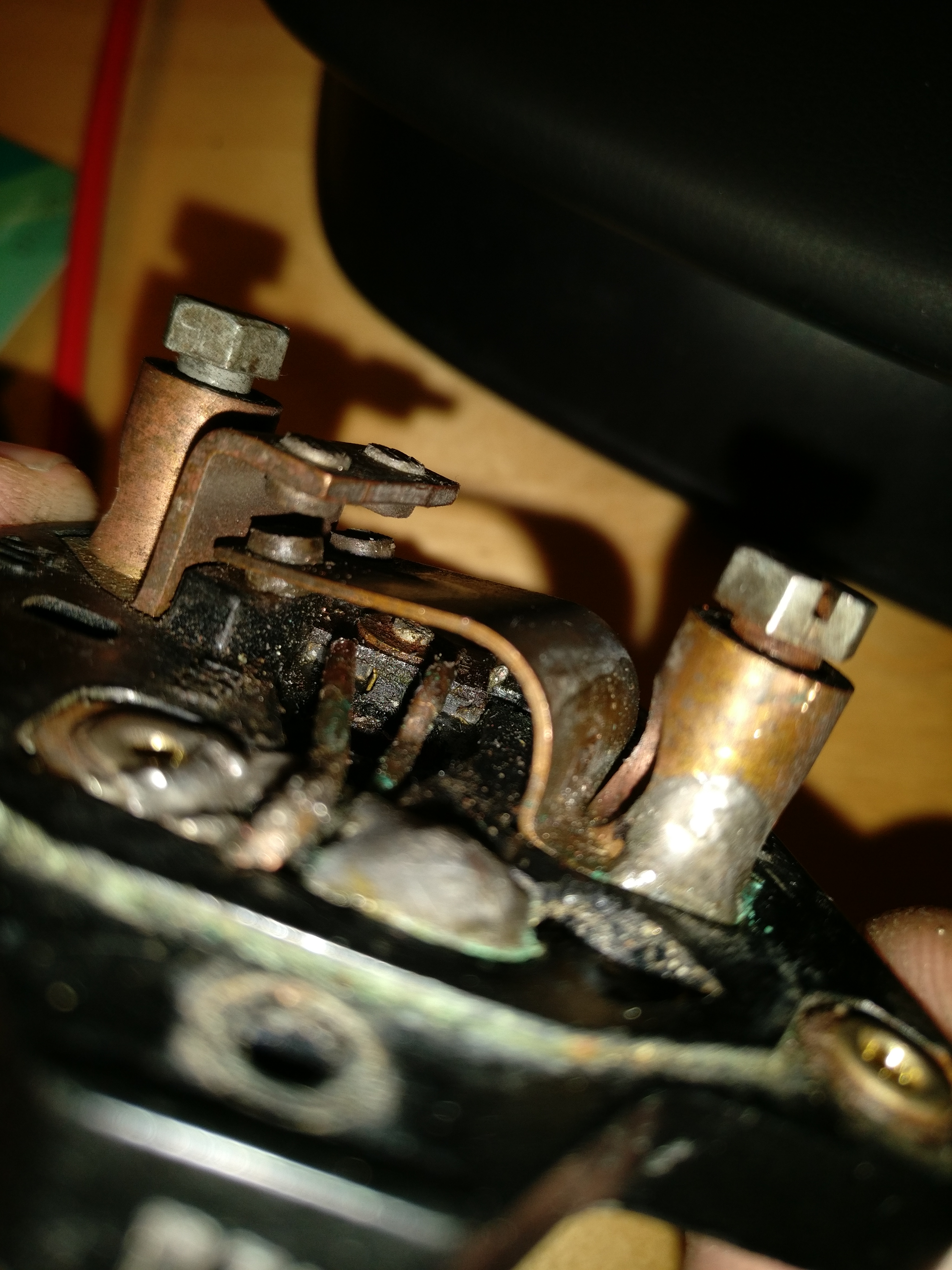
You can see the two copper contacts here:
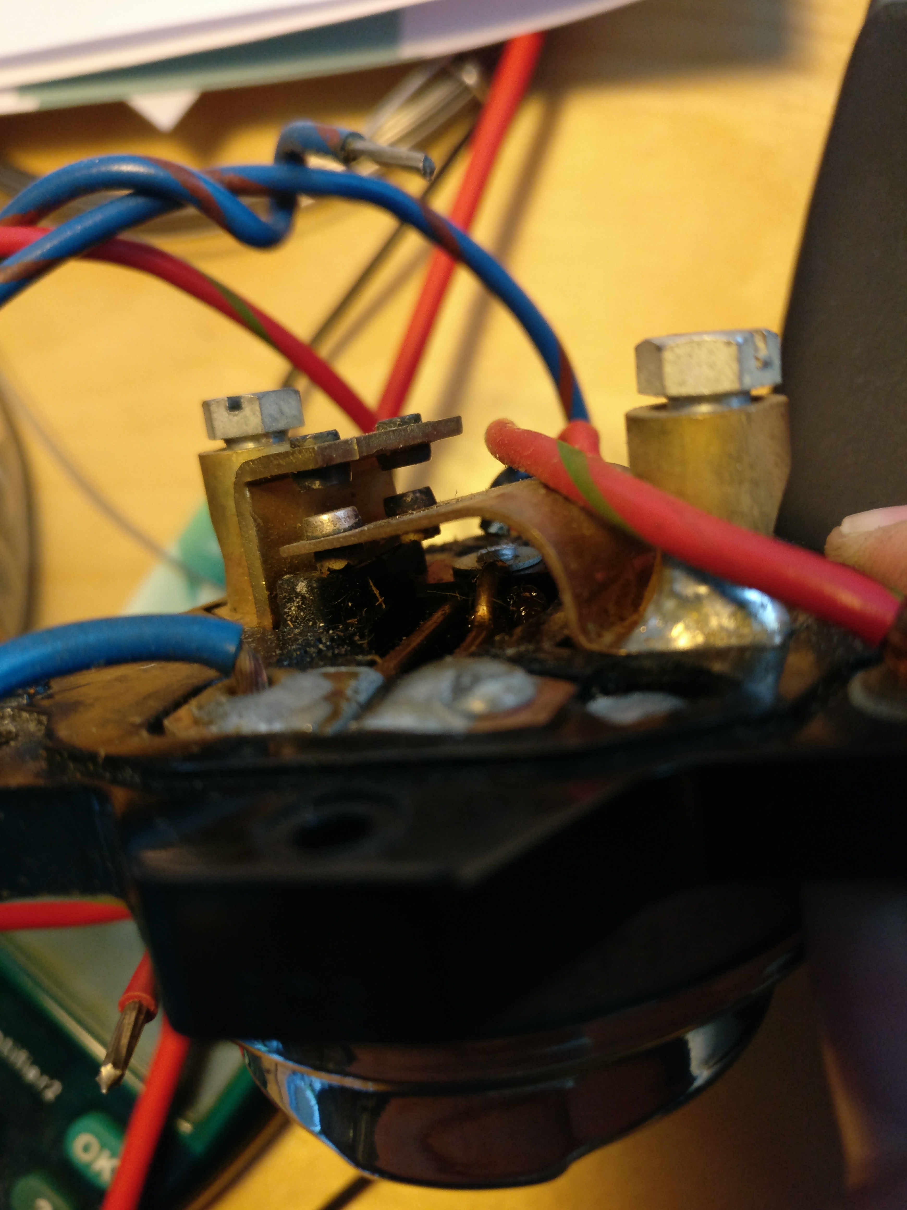
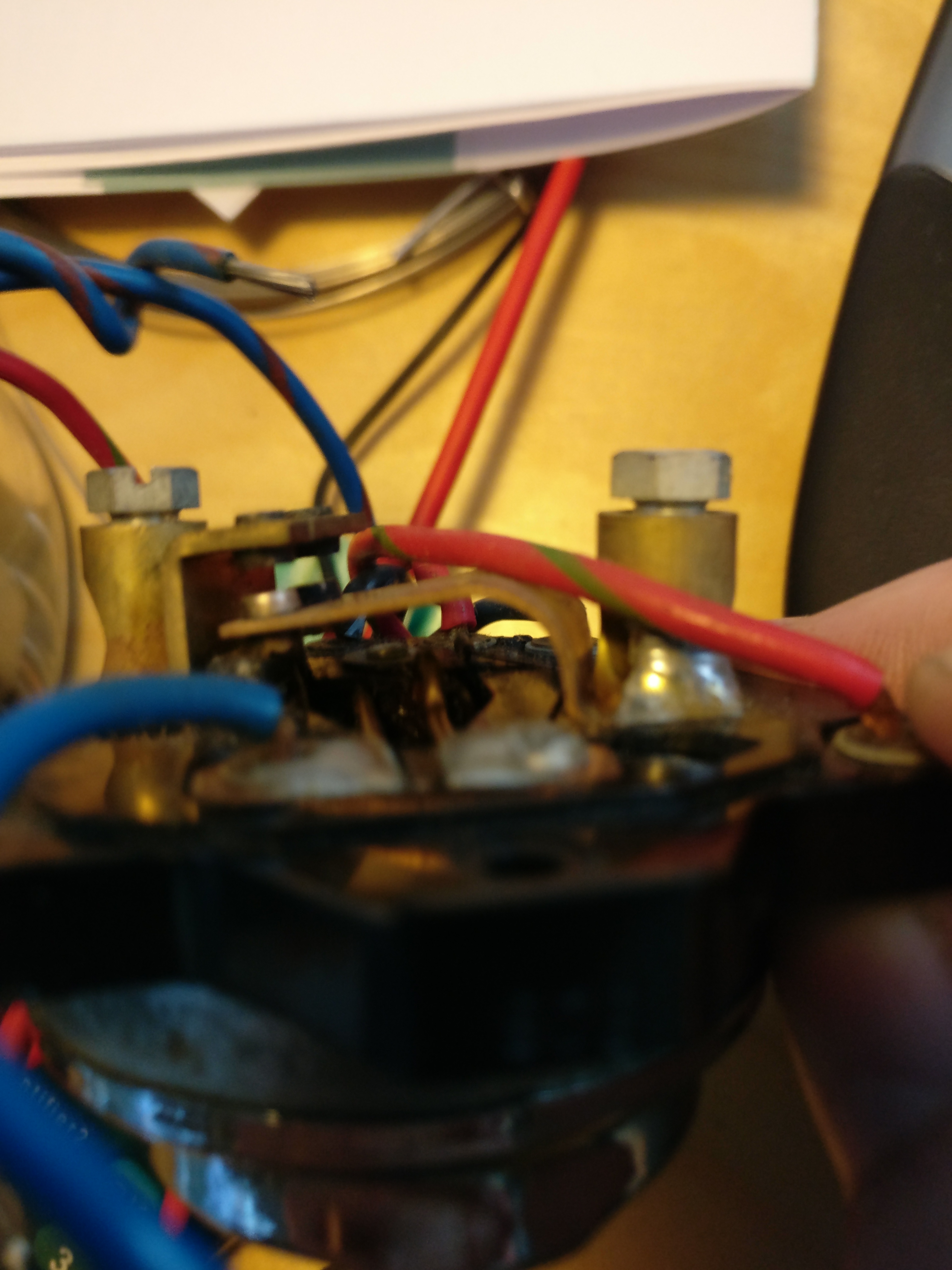
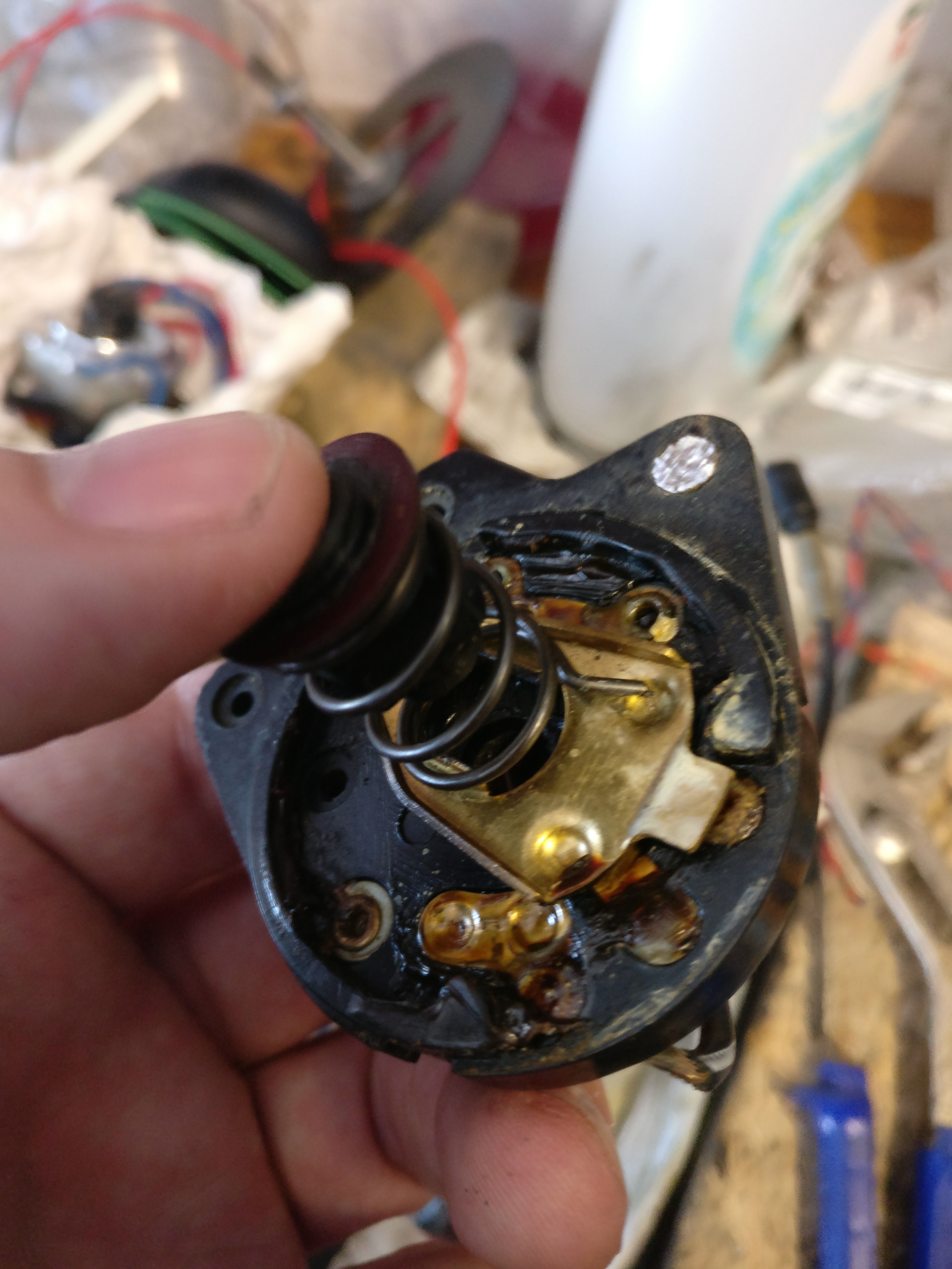
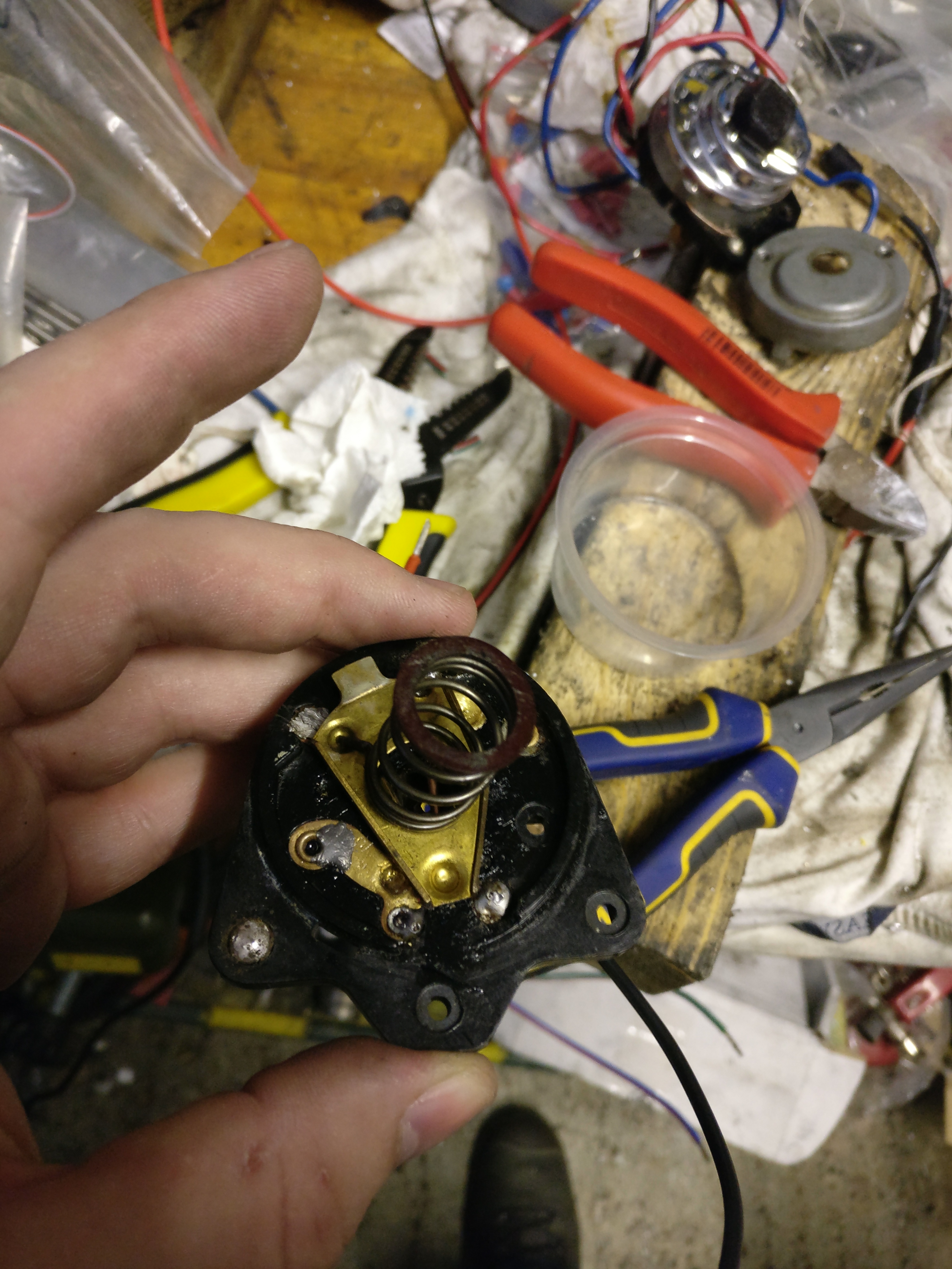
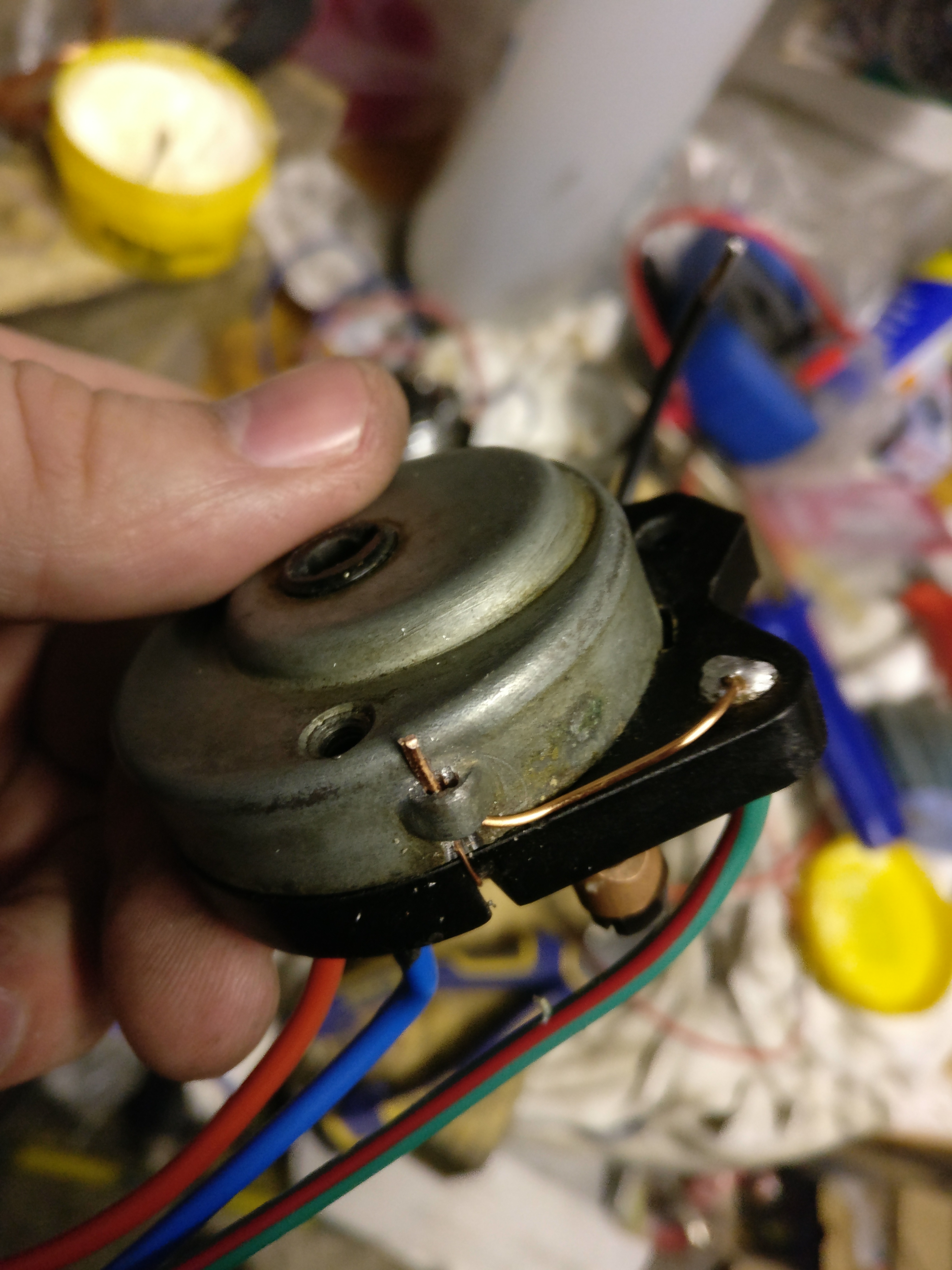
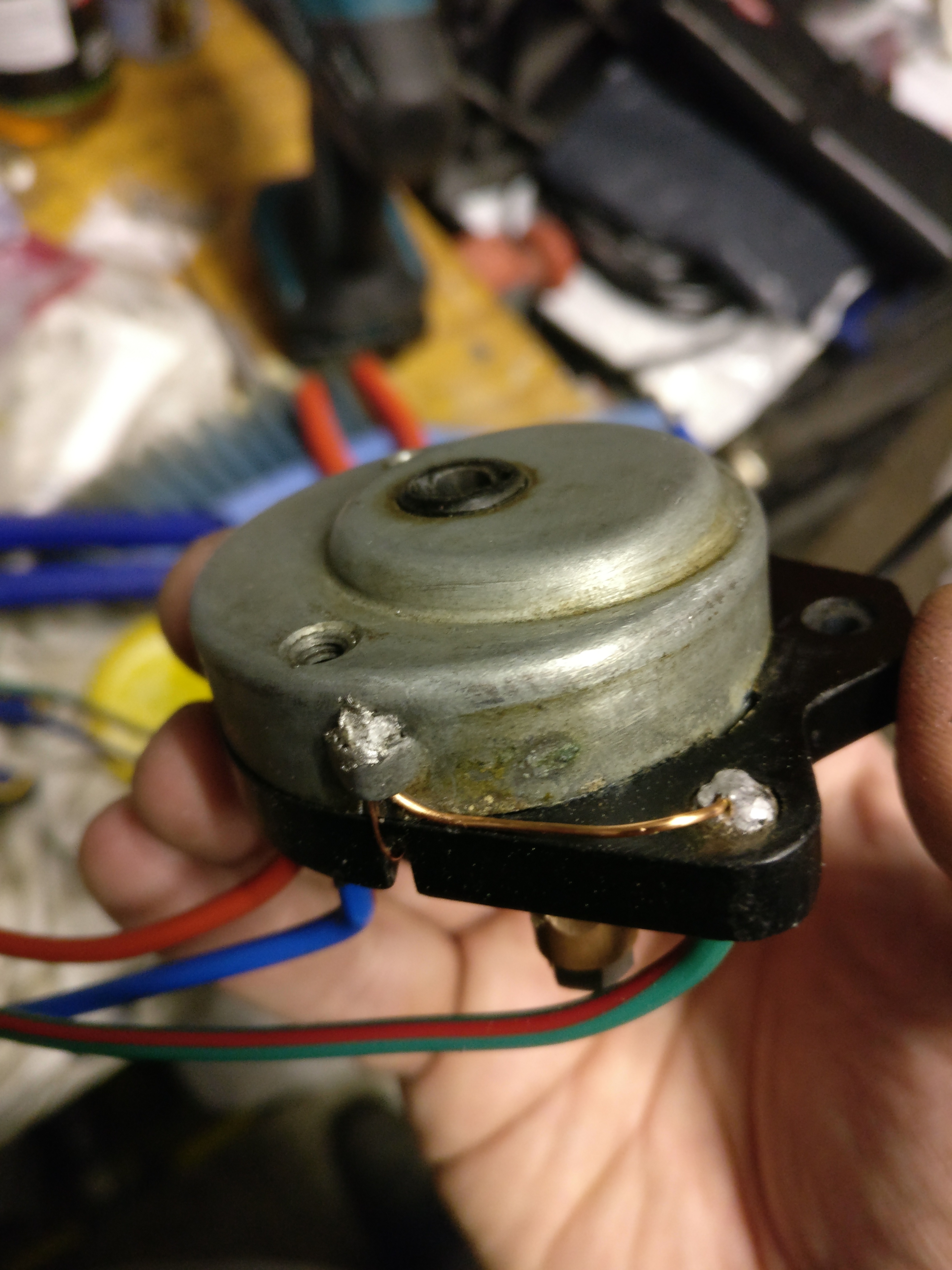
The switch to be repaired has a number of almost broken off wires and one of the two large copper wires is broken:
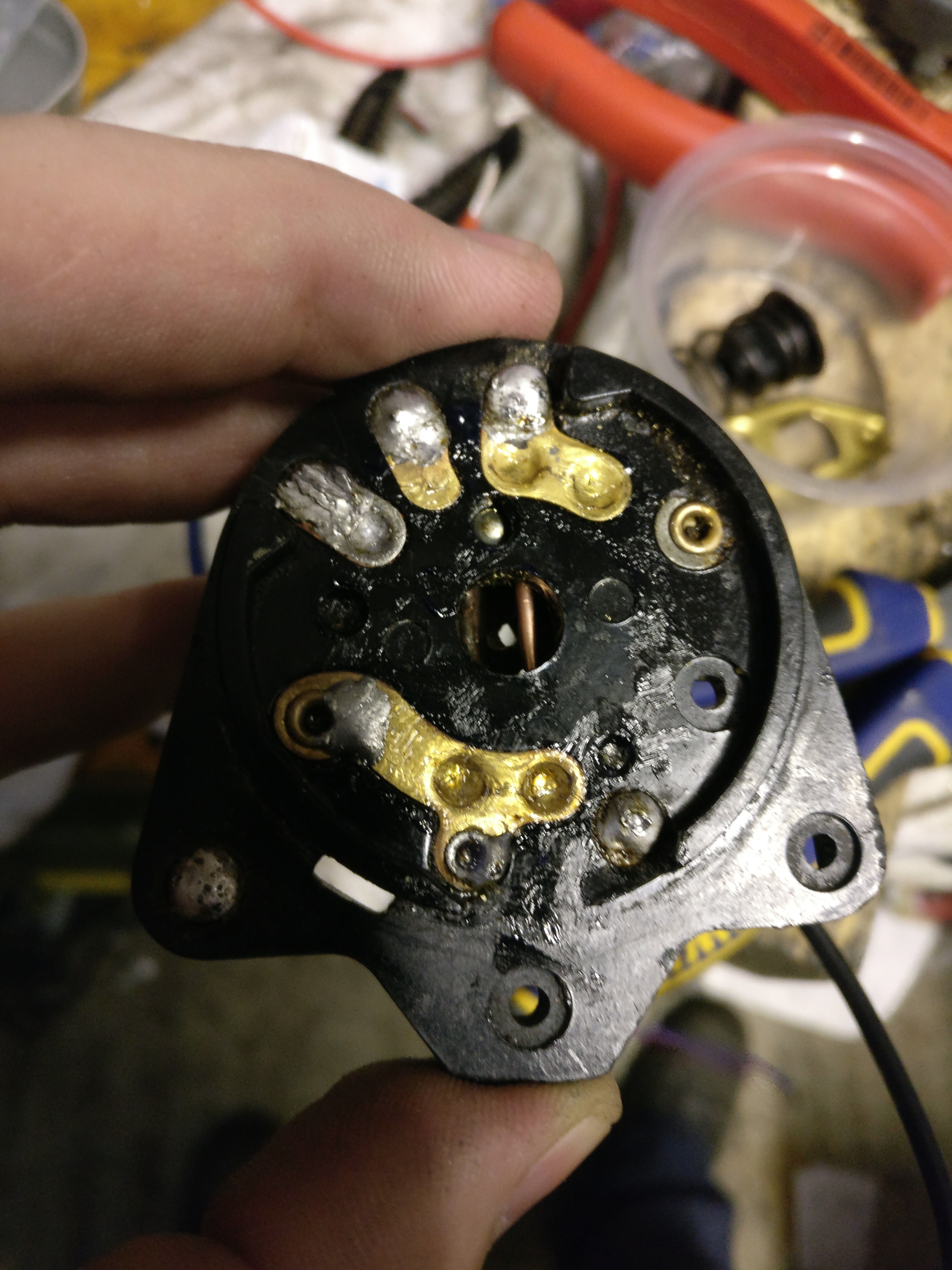
First step is remove the old solder and old wiring:
It’s a fiddly job – use a large soldering iron (300 watt) to remove the wires and old soldering – then drill out the eyelets carefully.
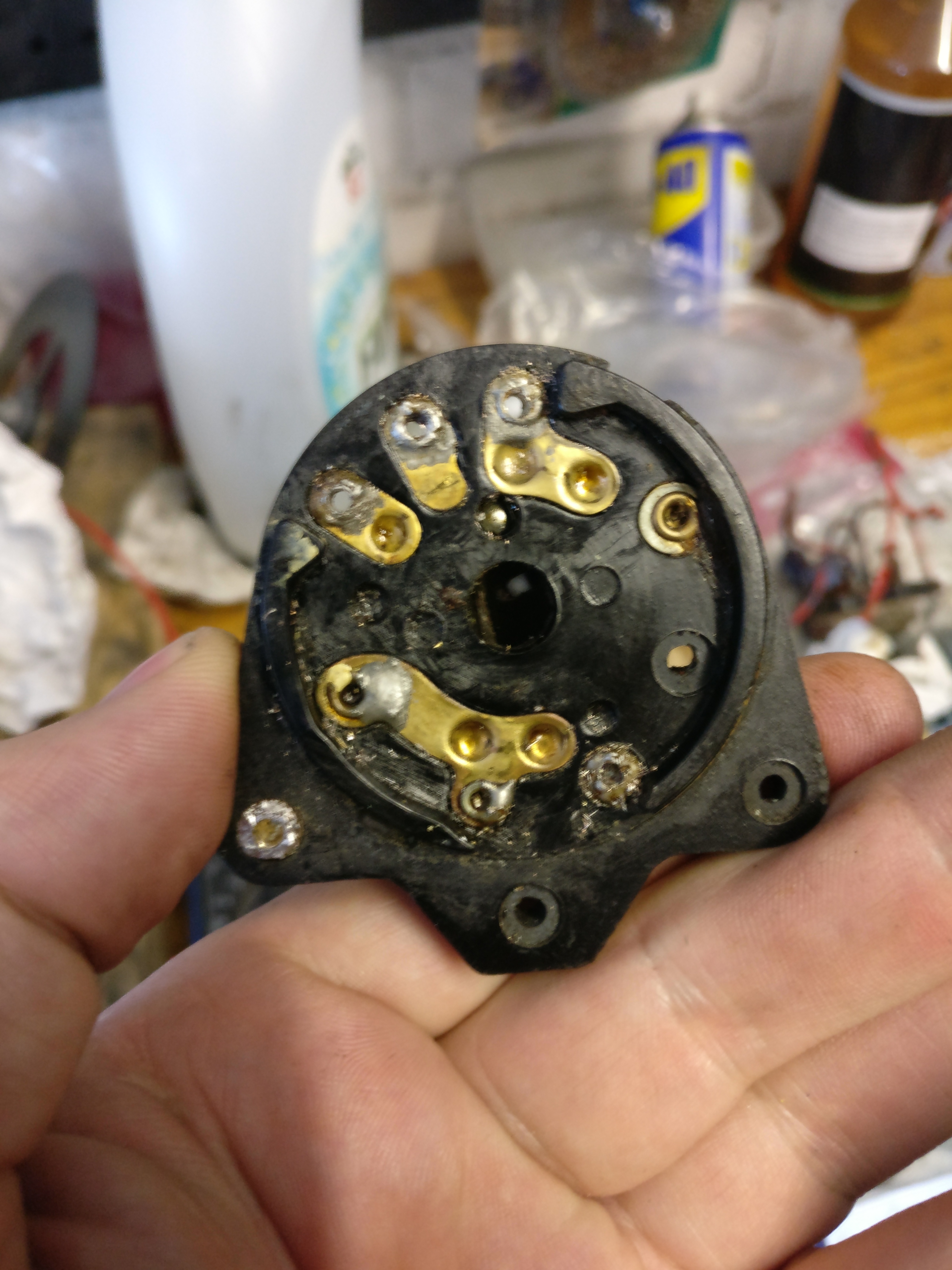
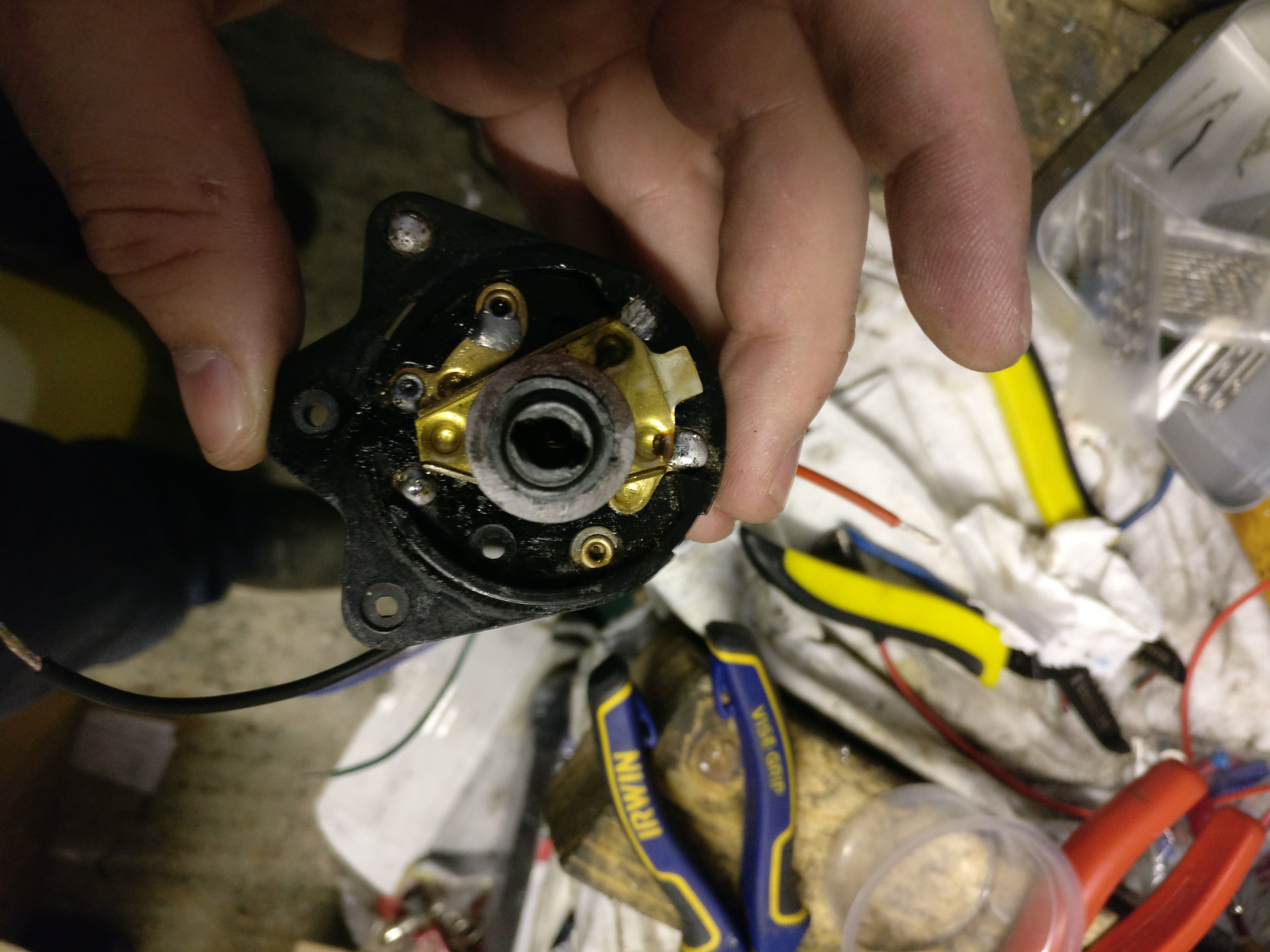
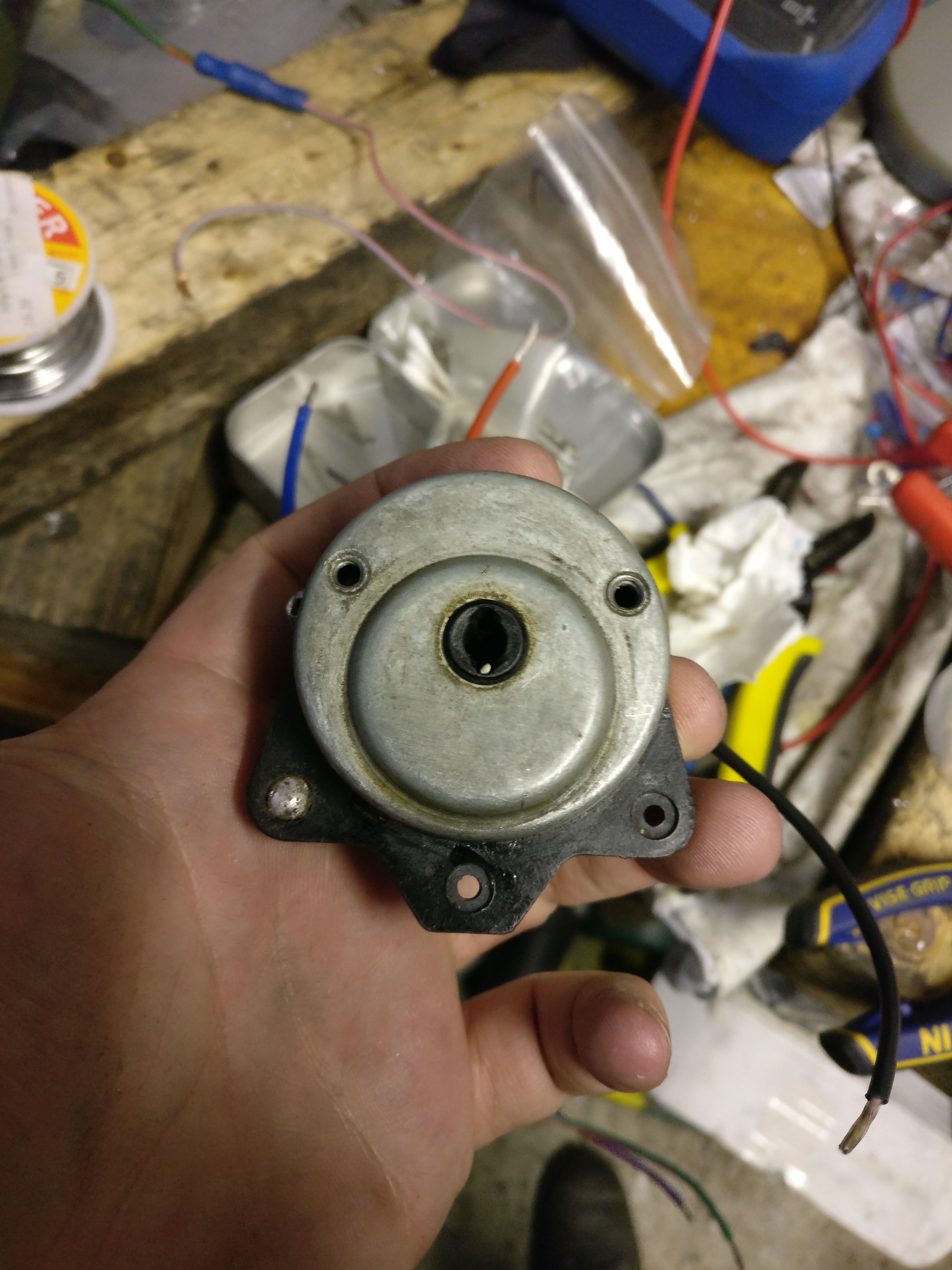
Then we’ll take the switch apart – this is required to drill out the remaining eyelets (otherwise metal shavings will be left inside the switch and cause a short circuit).
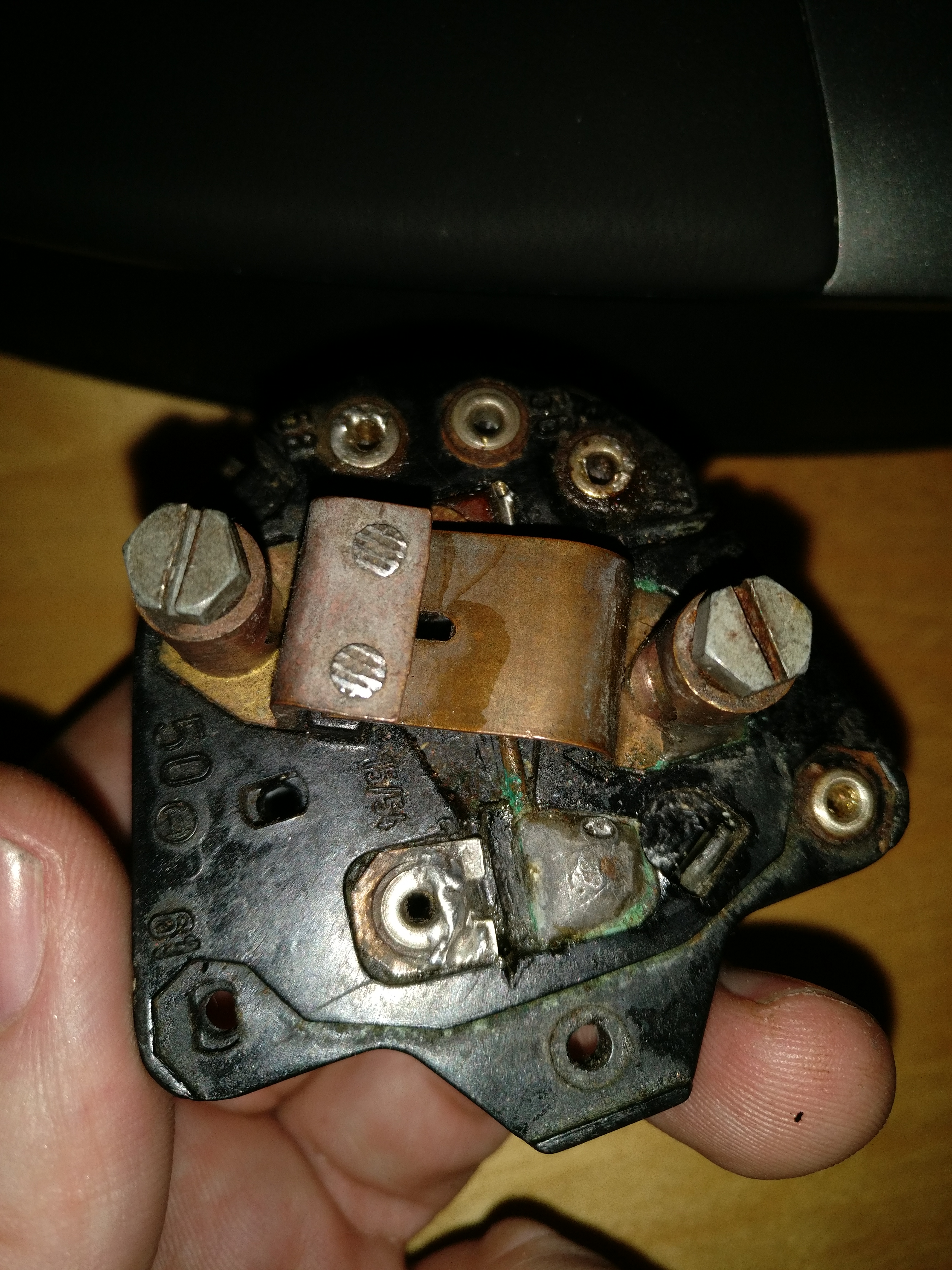
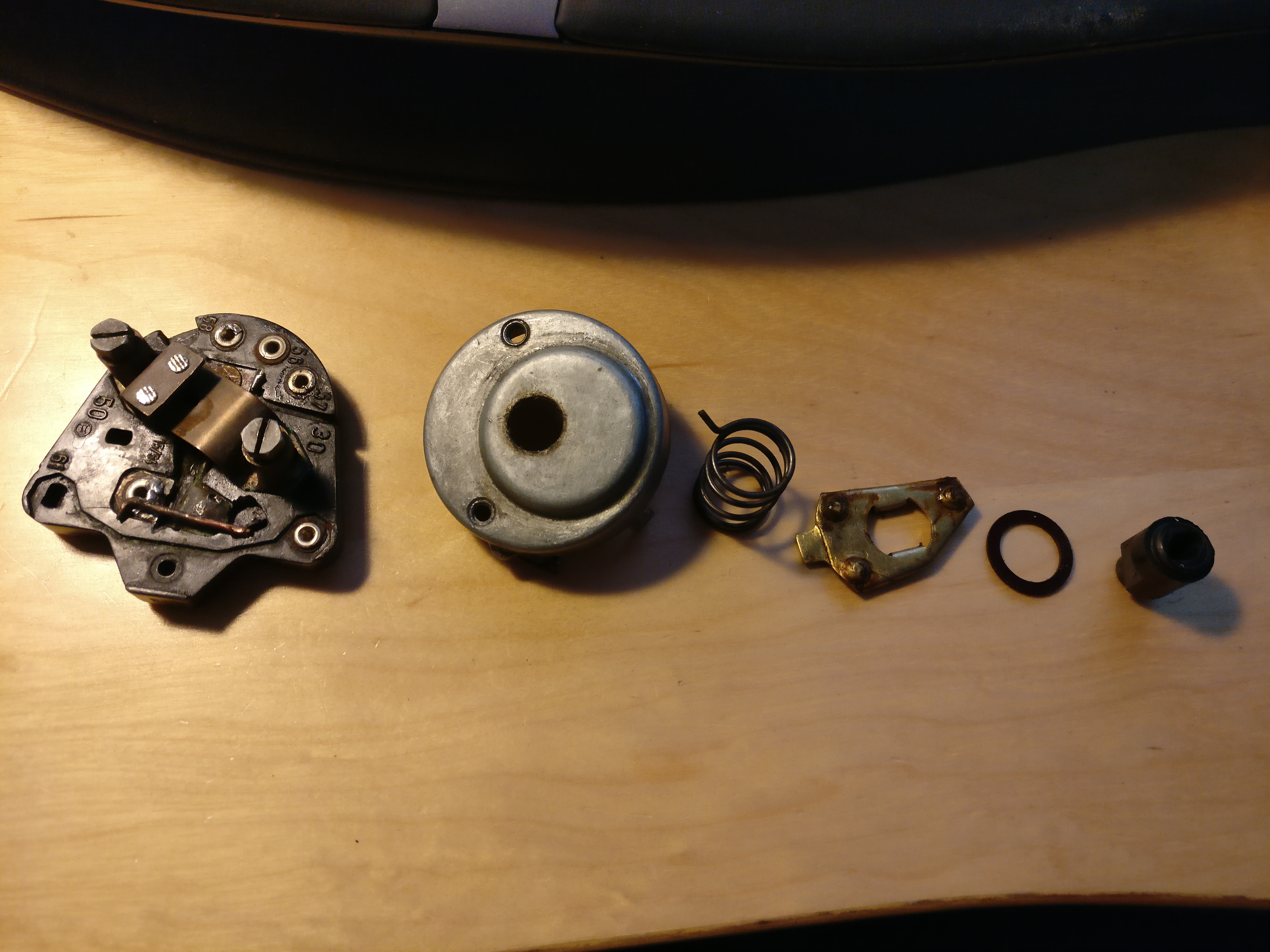
The switch in parts looks as follows:
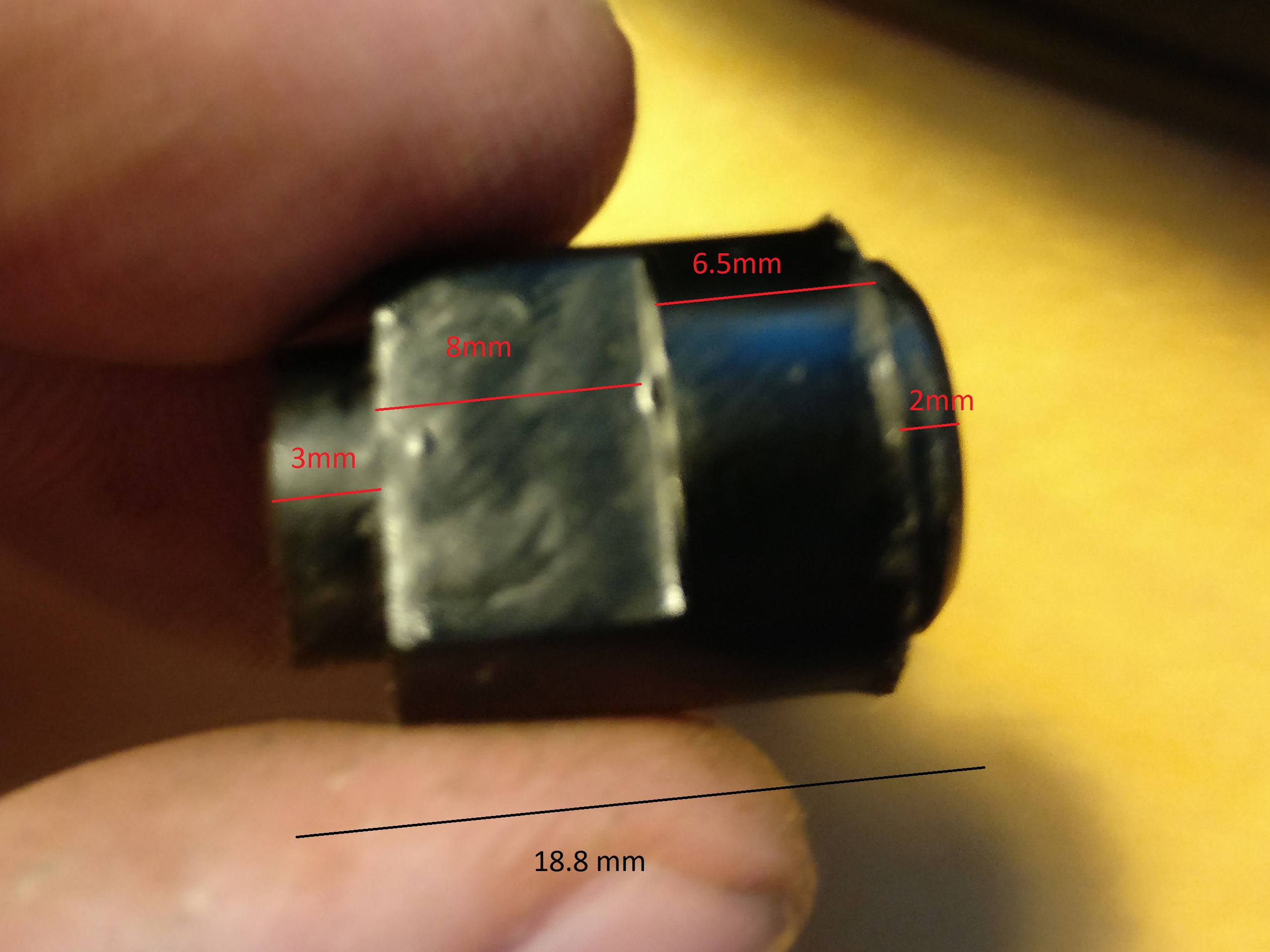
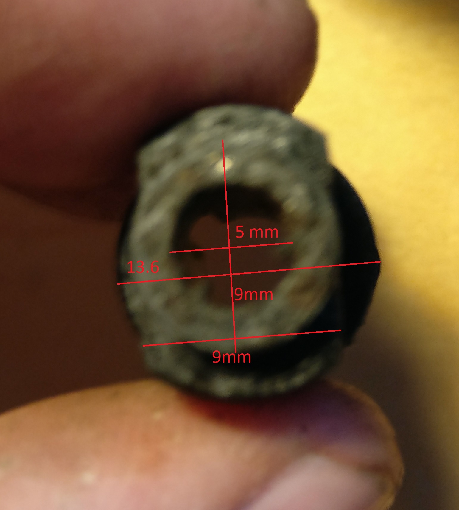
I’m taking the measurement of the central component in case it ever needs reproducing in a 3D printer.
The copper wire broken off looks as follows and is 1.75mm thick:
Now we know what we’ve got, next step is to order replacement wires and clean the switch up.
I put the whole switch in some copper and brass clean to get the worst of the corrosion off. Result:
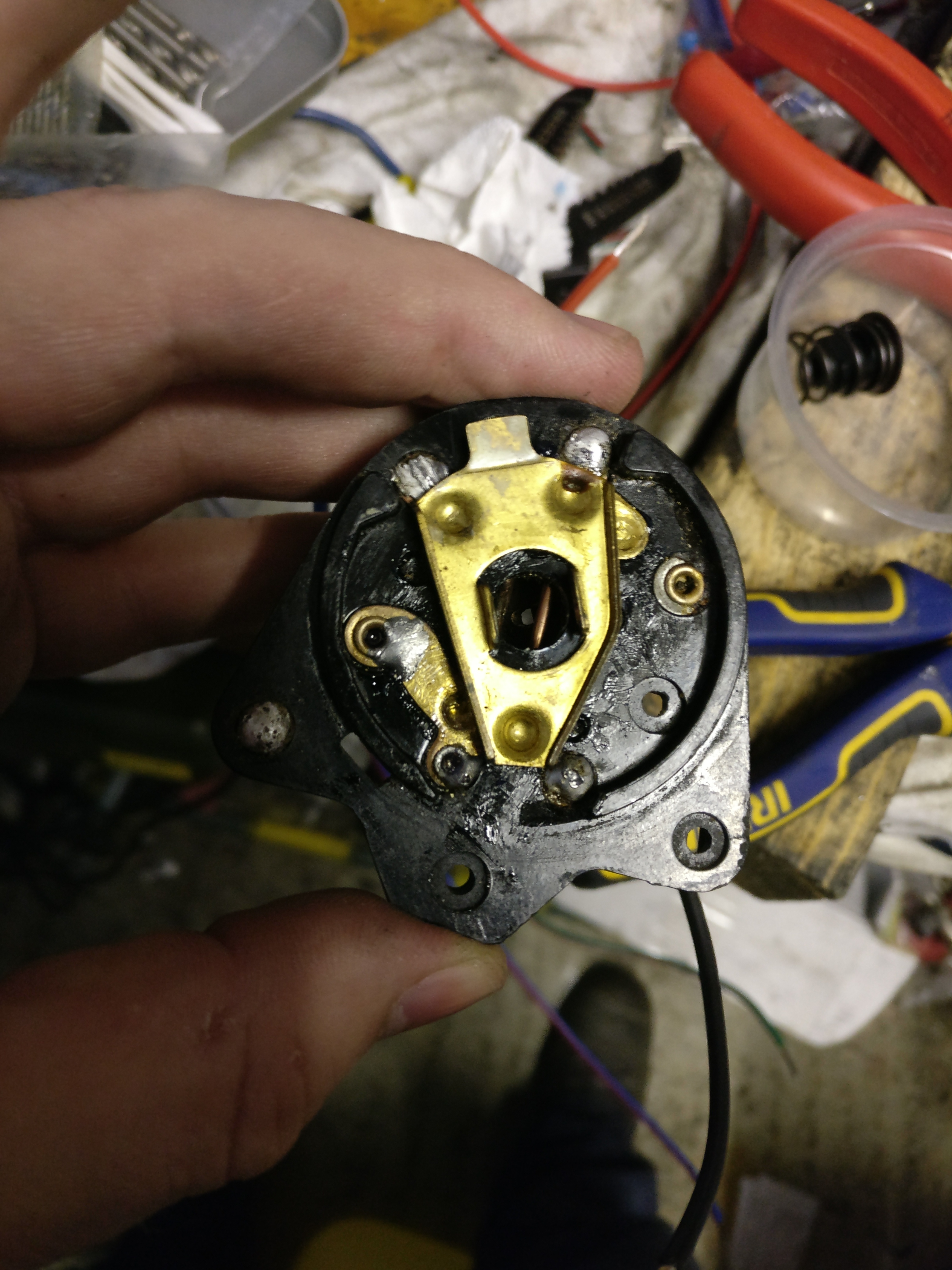
Next I put the replacement contact part in:
Next is soldering the contact in as well as replacement wiring. Note the 0.4mm wire which acts as a fuse:
Next we put the switch back together. You can see that the switching part has a protrusion that fits at the top so it limits movement. We put the spring on top and anchor it in one of the depressions. Then we put the non-conducting ring on top, add the plastic and close the switch back up. Note the plastic ring is slightly off-set so put it together so the slot is vertical when in it’s most left setting:
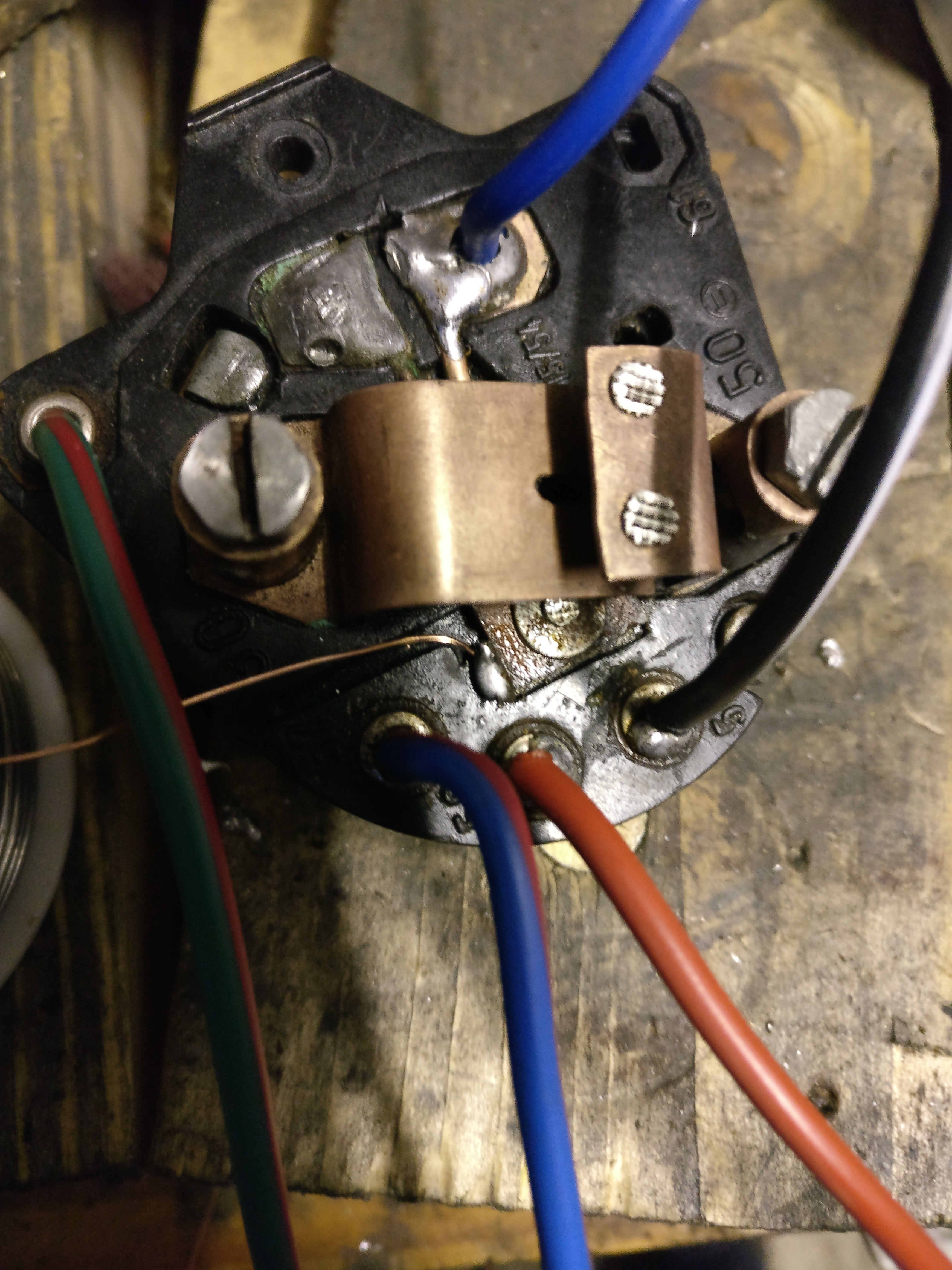
Finally we close the switch and route the 0.4mm through the hole, add the 0.8mm wire (grounding) and solder them in place:
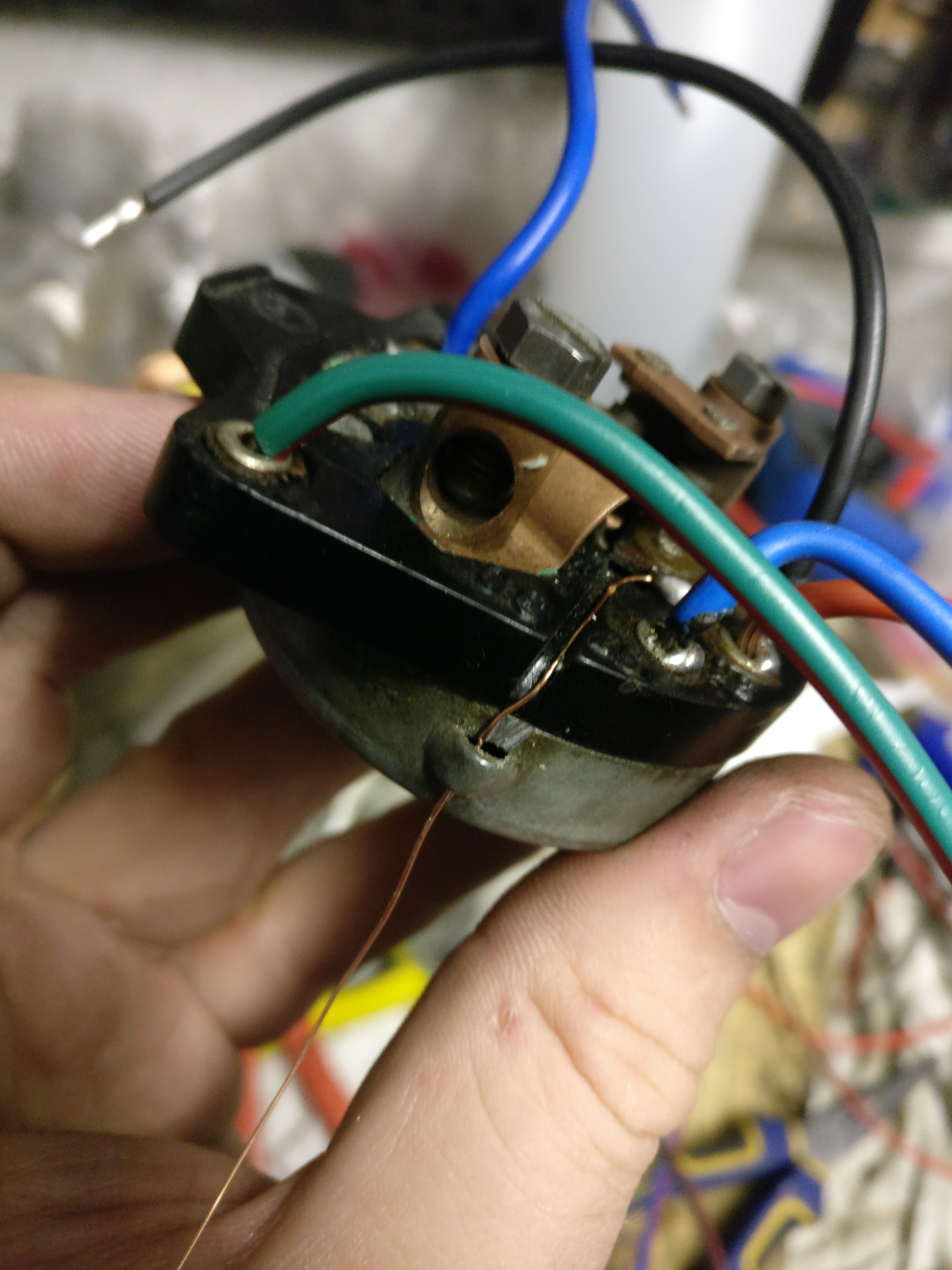
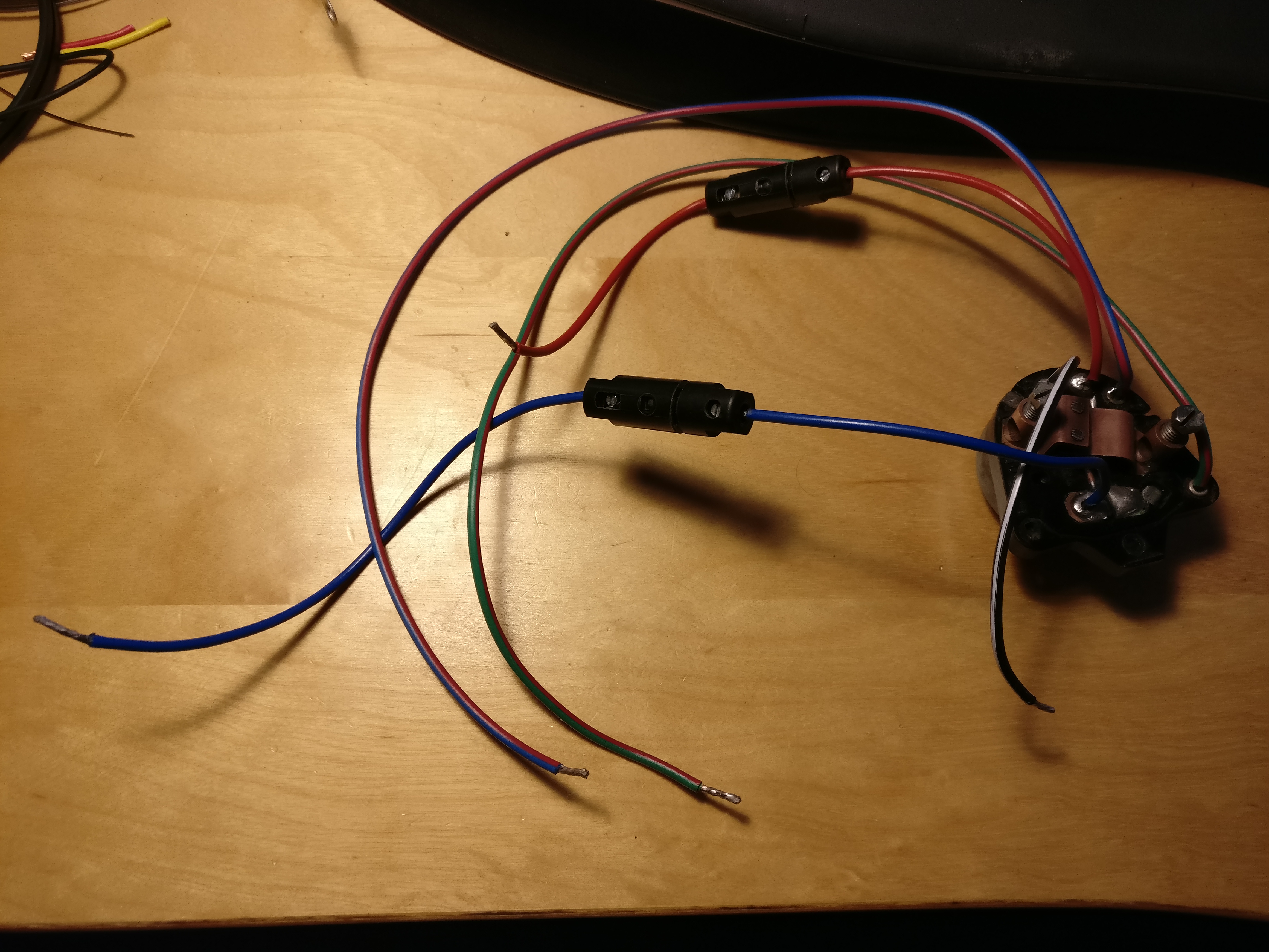
Note, before closing the switch I added some non-conducting grease. The final product looks as follows. I used slightly longer than original wiring (always convenient) and added two fuses; one for the lights (red wire) and one for the main power (blue).
So operation switch appears a success. The one doubt I have is that the new wire in the switch is made of copper that seems a bit softer than the original wire. It’s 1.8mm rather than 1.75mm of the original, but it appears that the original wire is a bit stronger. As the key needs to be held tight between the wires I hope this works. In a next attempt I would probably use a stainless steel wire, but as this is now in let’s see whether it lasts.
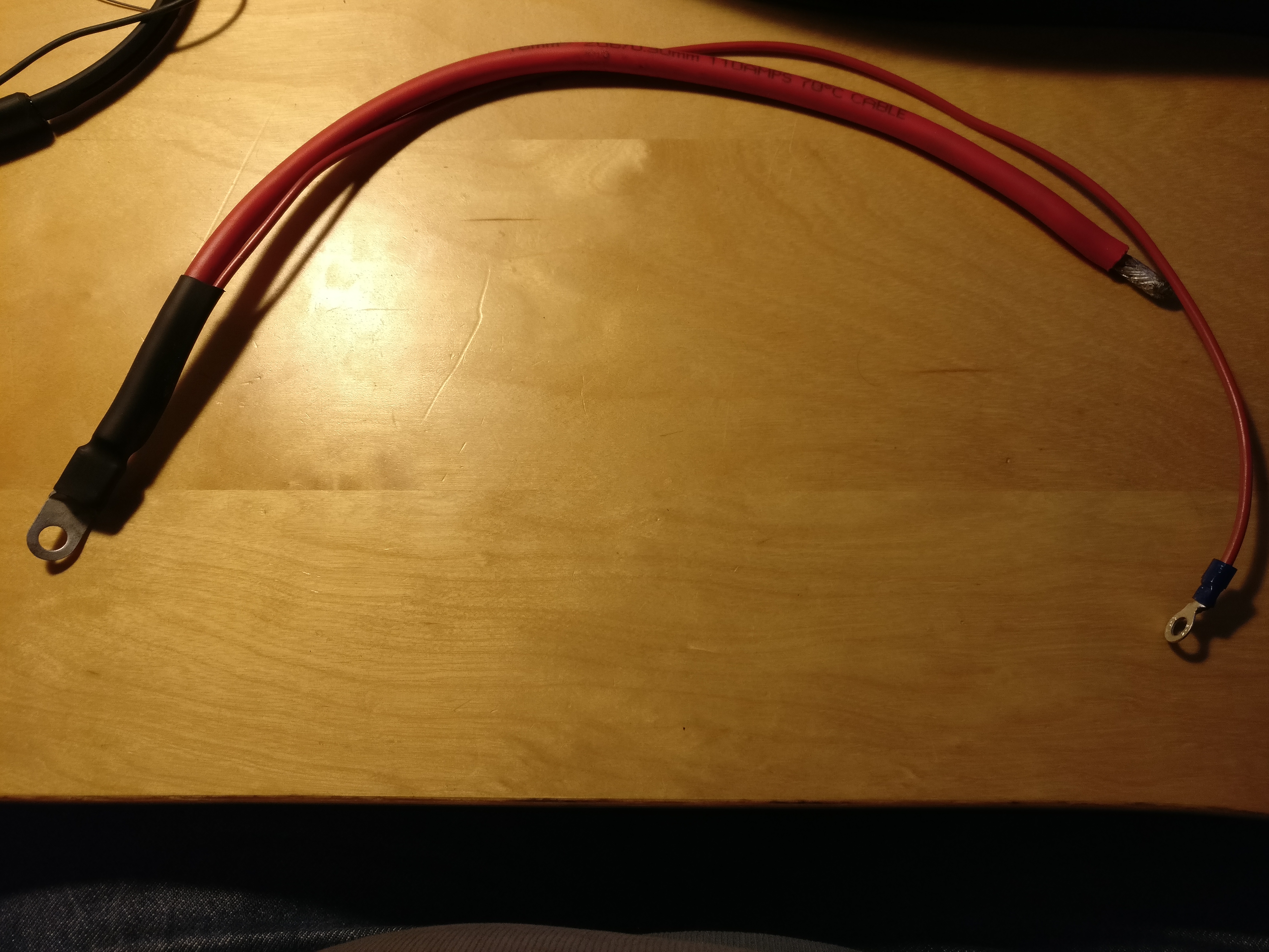
Also created a replacement battery feed as the old one was shot: